One Digital Model, Several Ways to Build It
A small bracket can emerge from a spool of plastic, a vat of liquid resin, or a bed of metal powder, yet each machine may be described simply as a 3D printer. That shared name hides major differences in how the object forms, which materials it can use, and what must happen after the build finishes. Understanding the process families makes the landscape easier to navigate without memorizing every machine brand or proprietary acronym. This guide explains the seven broad categories of additive manufacturing, places familiar technologies within them, and shows where specialist methods extend those ideas. The aim is to help beginners, designers, and curious workshop owners recognize what a process actually does. Once you can distinguish extruding, curing, fusing, bonding, and depositing, product descriptions become much more useful, and comparisons between desktop printers and industrial equipment stop feeling like comparisons between unrelated worlds.
A: Seven families organize the main joining and deposition mechanisms.
A: It belongs to material extrusion.
A: Both selectively cure resin in the vat photopolymerization family.
A: Surrounding polymer powder supports much geometry, although cleanup access remains necessary.
A: One deposits a binding agent into powder; the other deposits the build material itself.
A: Suitable directed energy deposition systems can support qualified repair or feature-addition work.
A: No; implementations can use polymer sheets or metal foils as well.
A: Their feedstocks and consolidation mechanisms may belong to different process families.
A: It does not identify the feedstock form, joining mechanism, or operations needed after material has been added.
A: It joins successive foil layers using ultrasonic energy and pressure rather than building through a moving bulk melt pool.
The Seven Families Behind the Names
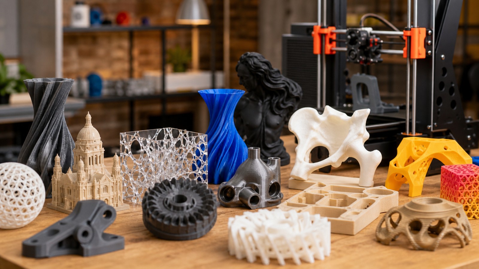
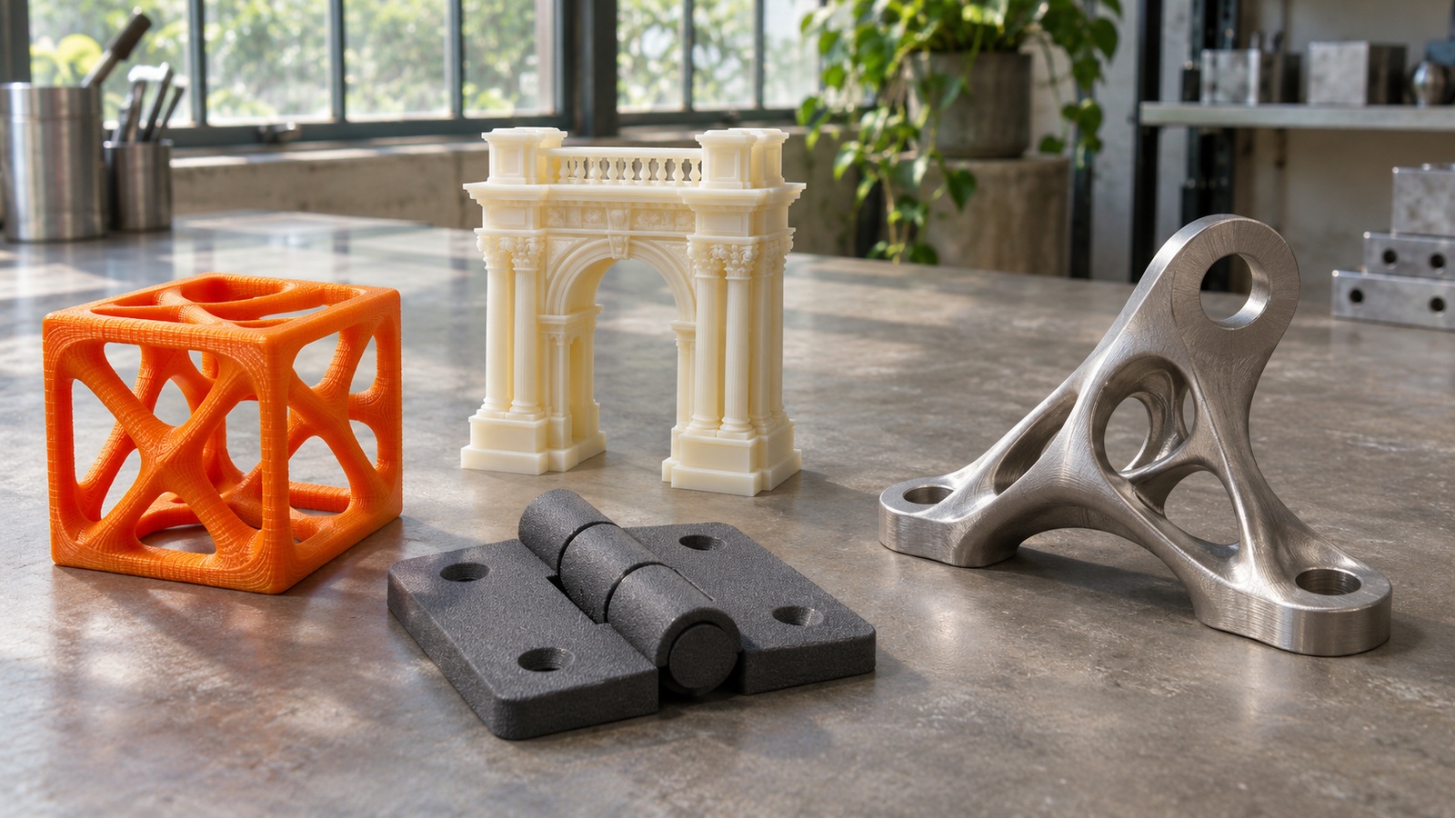
Additive manufacturing builds a physical object by adding material according to digital geometry, usually in successive layers. The seven widely used process families are material extrusion, vat photopolymerization, powder bed fusion, material jetting, binder jetting, directed energy deposition, and sheet lamination. These categories describe the mechanism that forms the part, rather than a particular material or commercial machine. A metal object, for example, could come from powder bed fusion, binder jetting followed by sintering, or directed energy deposition.
Names within a family often identify an energy source, a feedstock arrangement, or a manufacturer’s implementation. SLA and DLP both belong to vat photopolymerization, while polymer SLS and metal laser powder bed fusion belong to powder bed fusion. The distinction helps explain why two technologies can share a basic operating principle yet produce different surfaces, support requirements, and properties. NIST’s overview of additive manufacturing technologies provides a useful reference for the major mechanisms discussed here.
Material Extrusion: Drawing With a Moving Nozzle
Material extrusion dispenses feedstock through a nozzle and places it where the model requires material. On a typical desktop filament printer, drive gears push thermoplastic filament into a heated hot end. The nozzle lays down roads of softened plastic that join into walls, internal structures, and successive layers. Fused filament fabrication, or FFF, is a familiar name for this approach; FDM is another widely encountered term associated with the same general filament-based method.
The moving nozzle makes the process approachable because you can watch the object develop and inspect the deposited paths. It also introduces recognizable constraints. Unsupported overhangs may need temporary structures, small details cannot ignore nozzle width, and a part’s resistance to loading can depend strongly on its orientation. Filament printers are useful for prototypes, fixtures, housings, and many practical workshop objects, but their visible layers and directional behavior require realistic expectations.
Extrusion is broader than ordinary plastic filament. Pellet-fed equipment handles granulated thermoplastic, paste systems deposit clay or other viscous feedstocks, and some composite systems combine an extruded matrix with reinforcing fibers. Bound-metal extrusion uses a mixture containing metal particles and binder, with later processing needed to produce the final metal component. The nozzle is the family resemblance; the complete production route determines what the finished object becomes.
Vat Photopolymerization: Turning Liquid Into Solid
Vat photopolymerization selectively exposes a liquid photopolymer to light so that chosen regions solidify. A photopolymer is a formulation that reacts to suitable light; it is not simply thermoplastic waiting to cool. Laser-based stereolithography traces areas with a focused beam, while projection and masked systems expose a layer through an image or mask. These approaches can reproduce small features and smooth-looking surfaces, which explains their use for miniatures, dental models, jewelry patterns, and detailed prototypes.
The freshly printed object still follows its material’s specified washing, drying, support-removal, and post-curing route. A resin’s formulation and completed processing help determine its properties, so a rigid display material and an engineering resin are different choices despite their similar appearance. Liquid handling requires the workspace and precautions described in the product’s safety data sheet. Detail depends on the optics, material, geometry, and preparation together, rather than the advertised pixel size alone.
Powder Bed Fusion: Joining Selected Regions of Powder
Powder bed fusion spreads thin layers of powder and applies energy selectively to build a cross-section. In polymer selective laser sintering, a laser joins suitable powder particles, commonly nylon-based materials. Surrounding powder supports much of the geometry during the build, allowing arrangements that would require extensive support scaffolding on many other printers. The powder still has to be removed afterward, and enclosed cavities need suitable escape routes. Cooling and powder handling contribute to the production cycle.
Metal powder bed fusion uses a laser or electron beam to consolidate metal powder into components. Metal builds often need supports to manage heat flow and distortion as well as hold geometry in position, so loose powder does not eliminate all support planning. Parts may also need heat treatment, separation from the build plate, surface finishing, and machining of critical interfaces.
HP Multi Jet Fusion is also a polymer powder-bed fusion route. Instead of tracing the selected regions with a laser spot, the machine applies agents across a powder layer and delivers infrared energy; the fusing agent helps the intended regions absorb energy and fuse. The mechanism therefore belongs with thermal powder fusion, even though droplets help define the layer. HP’s process diagram shows powder recoating, agent application, energy delivery, and the resulting fused section. The crucial distinction from binder jetting is what joins the build material: fusion of the polymer rather than an adhesive bond awaiting a different consolidation route.
Material Jetting: Placing Droplets Where They Belong
Material jetting deposits droplets of build material in selected positions. In common photopolymer systems, the deposited droplets are cured with light, and separate support material helps hold unsupported regions. Depending on the equipment, the process can combine different colors or materials within one build. This makes it valuable for realistic appearance models, anatomical teaching models, and prototypes where the relationship between soft and rigid regions needs to be demonstrated.
A realistic appearance model can answer questions about shape and color without reproducing the aging or mechanical behavior of the intended production plastic. Choose whether the job is communication, fit checking, or a representative functional test before selecting its material combination. The support-removal route also matters: a narrow channel may be printable yet inaccessible for cleanup. For an intricate model, discuss where support will sit and how it can leave before approving the geometry. Judge the process through the cleaned model that will be handled, rather than only its attractive digital preview.
Binder Jetting: Printing a Bond Into a Powder Bed
Binder jetting selectively deposits a liquid binding agent into powder, creating a bonded shape rather than directly melting the entire cross-section. The next steps depend on the material system: sand molds may be prepared for casting, while many metal parts require curing, depowdering, debinding, and sintering. Before consolidation, a metal component can be fragile, and furnace processing introduces shrinkage that the production route must account for. The attraction is a different combination of build productivity, material possibilities, and support conditions from beam-based fusion. However, a fast printing stage does not establish a fast delivery date by itself. Powder removal, furnace capacity, dimensional control, and inspection can determine the practical throughput of the complete operation.
Directed Energy Deposition: Adding Material Into a Melt Pool
Directed energy deposition supplies material to a region where focused thermal energy melts it as it is deposited. Feedstock may arrive as powder or wire, and the energy source can vary. Rather than drawing every layer inside a flat powder bed, the deposition head often works with a moving platform, robotic system, or multi-axis machine. This arrangement is useful for adding material to an existing component, building large metal forms, or producing features that will later be machined.
Repair is an especially helpful way to understand the process. A worn region can sometimes receive additional material, followed by machining to restore the required surface. That possibility depends on the alloy, the condition of the original part, the process qualification, and the application’s acceptance requirements. Deposited beads are often coarser than fine powder-bed features, so directed energy deposition should be judged by its ability to place material efficiently and integrate with finishing, rather than by miniature-detail expectations.
Sheet Lamination: Building From Bonded Layers
Sheet lamination joins layers of sheet material and forms the required shape through cutting and bonding operations. Different implementations use materials such as paper, polymer sheets, or metal foils, so the joining mechanism and resulting properties vary considerably. Some approaches cut each layer before or after it is bonded into the stack. Others integrate consolidation and machining operations to produce the final geometry.
Ultrasonic additive manufacturing is a metal-foil example that uses ultrasonic energy and pressure to join layers. This provides a useful reminder that additive manufacturing does not always involve a glowing melt pool, liquid resin, or a heated filament nozzle. The family is defined by its layered sheet feedstock and joining approach. Its practical limits depend on bond quality, access for tooling, material combinations, and the geometry that remains after surrounding material is removed.
Sheet-based processes are less familiar to many desktop users, but excluding them would leave an incomplete picture of the field. They show how broad the term 3D printing has become in everyday language. Whenever a process description seems unfamiliar, ask what form the feedstock takes, how the material joins, and how the unwanted material leaves. Those three observations usually reveal more than an isolated acronym.
Why Orientation Changes the Same Object
A digital model has no preferred direction until the manufacturing plan gives it one. Rotating the model changes which surfaces face downward, where supports attach, and how successive layers carry loads. On a filament bracket, the layer interfaces may become an important weakness if the load pulls them apart. On a metal component, orientation can affect thermal management and the amount of material needed for supports. These effects belong to the process explanation because they help account for why identical geometry can lead to different results.
There is rarely one orientation that optimizes every requirement. A smooth display face might compete with easy support removal, and a compact build arrangement might place a critical bore in an unfavorable direction. Experienced operators balance those priorities using the purpose of the part. Ask to see the proposed orientation when reviewing a production plan, especially if the sample looks very different from the view used in the original CAD model.
Specialist Applications Still Need a Complete Process Chain
Bioprinting, construction printing, continuous-fiber fabrication, and hybrid manufacturing are often presented as if each were a single additional process family. In practice, these labels may identify an application area, a feedstock strategy, or a combination of operations. Construction equipment may extrude a cementitious mixture; a hybrid machine may combine metal deposition with CNC machining. Understanding that distinction prevents application labels from obscuring the physical method used to make the object.
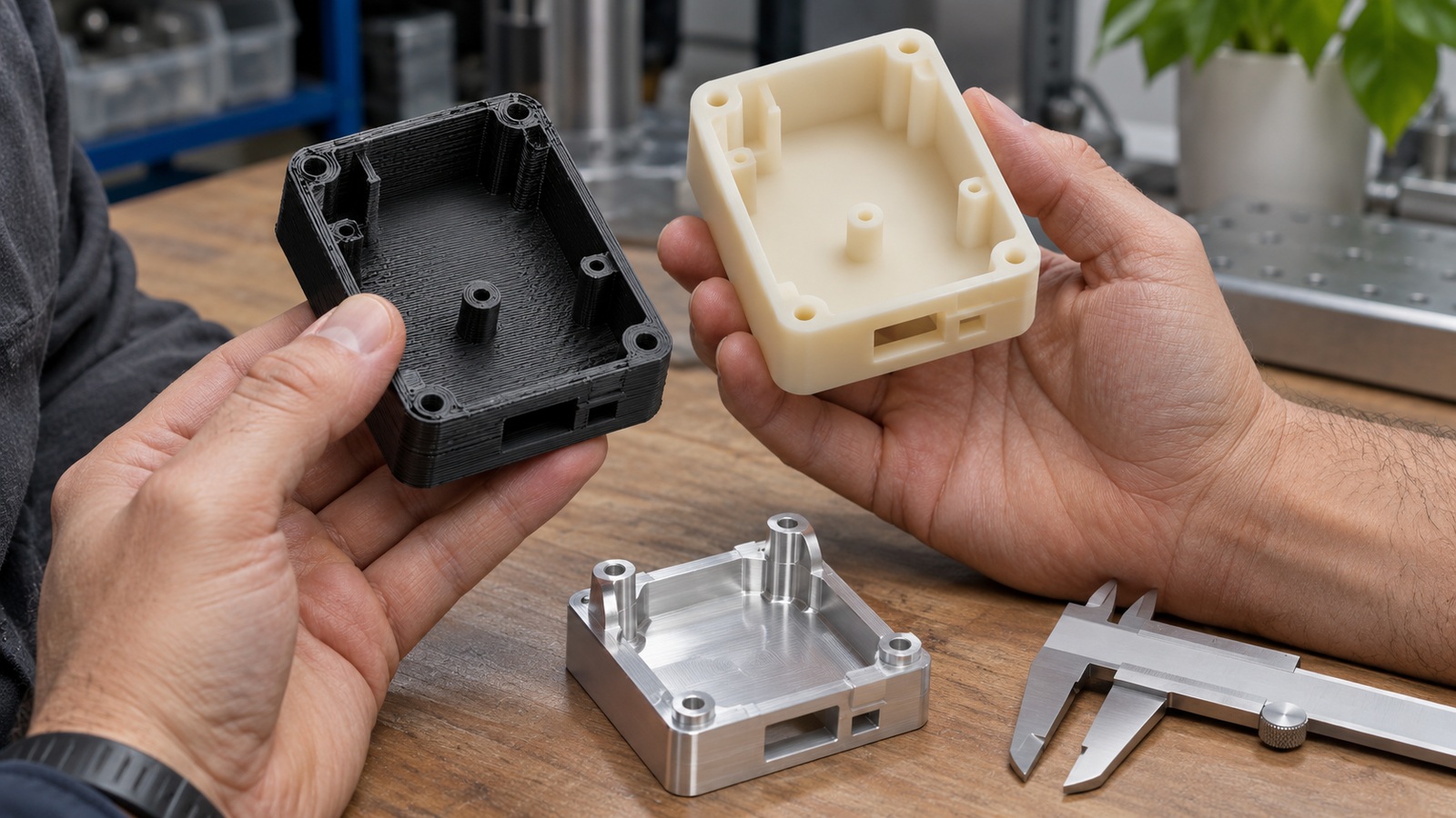
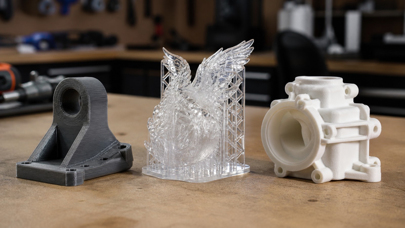
Return to the small bracket from the introduction. A filament version can help a designer hold its shape against neighboring hardware and revise a misplaced opening quickly. A resin version can make a tiny embossed symbol easier to study, but its material and cured condition must suit any test beyond appearance. A metal powder-bed version changes the material opportunity and adds a route through build recovery, support work, and any required machining. These are different ways to investigate or manufacture the bracket, not three machines producing interchangeable evidence.
The family name explains how each version forms. The part’s purpose explains which version is useful: an early spatial mockup, a detailed visual proposal, and a metal service component ask different questions. Once feedstock, joining mechanism, and delivered condition are clear, unfamiliar machine names become easier to interpret. You can place the process on the map and then examine whether its particular implementation fits the object you actually need.