Find the First Thing That Went Wrong
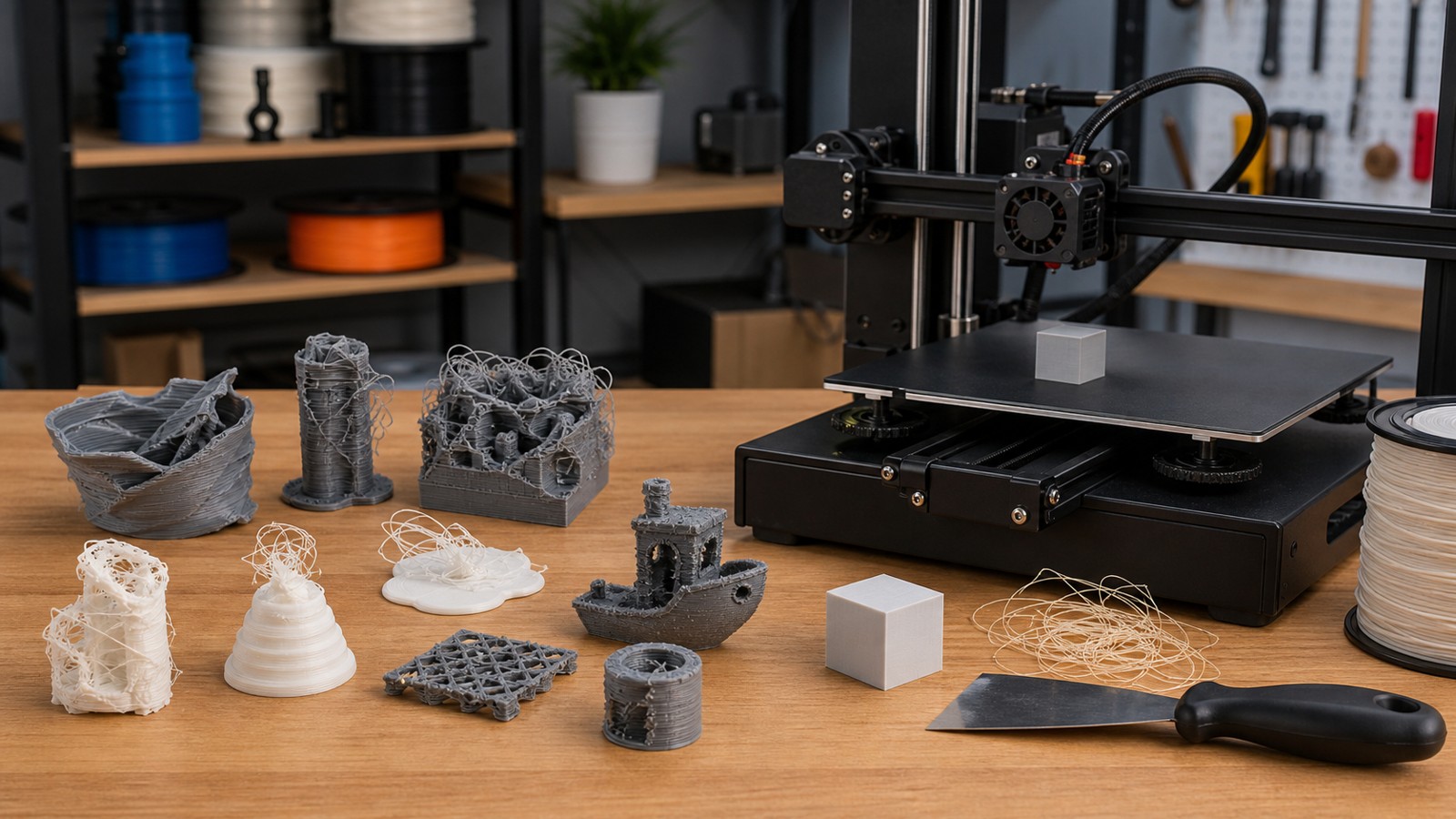
A nest of loose filament at the end of a failed build is an outcome, not a complete diagnosis. The object may have detached an hour earlier, a narrow support may have collapsed, or the nozzle may have struck a region that was already curling upward. The most useful starting point is the earliest visible departure from the intended print. That clue tells you which part of the workflow deserves attention and prevents a dramatic final mess from sending you toward an unrelated adjustment. This guide organizes common failures by what you can observe: an uneven first layer, a lifted base, missing material, stray strands, shifted geometry, or features that never appear. Most examples concern desktop filament printing, with a separate discussion of resin-specific failures. Use the symptom to narrow the field, then follow the relevant equipment and material instructions before attempting a repair or changing the production setup.
A: The feature may fall below the process’s practical detail limit or lack enough support to survive formation. Compare its actual thickness with the machine and resin guidance, rather than assuming the whole exposure failed.
A: The slope crosses discrete layer heights, creating a staircase. Compare those expected steps with the sliced geometry before interpreting them as a new motion fault.
A: The nozzle may be contacting or dragging over the formed surface during travel. Inspect the path and excess-material conditions instead of treating every mark as a gap needing more flow.
A: Bands can reflect repeated variation in deposition or Z motion without moving the whole upper model sideways. Compare their spacing with the mechanical and temperature behavior described by the printer’s troubleshooting guidance.
A: That can be pillowing over the internal structure. Check the top-layer arrangement and cooling guidance rather than assuming every surface hole is a nozzle blockage.
A: Ringing can follow vibration excited by the direction change. Inspect the machine and its supported motion settings; a whole-layer displacement is a different symptom.
A: A repeated location across different models warrants inspection of the relevant release surface and exposure hardware through the maker’s test procedure. Increasing exposure everywhere may miss a local problem.
A: In bottom-up printing, an unresolved cup can trap air and develop a pressure difference during separation. Review orientation and venting using the resin system’s cupping guidance; this is a force problem as well as a hollow-model design issue.
A: Melt can escape while the hot end is heated even before the object toolpaths start. Distinguish that warm-up behavior from a fresh leak at an assembly joint.
A: Inspect the prepared job for an intentional color-change or pause command. A scheduled instruction is different from a motion or feeding failure.
Decide Whether the Problem Began Before Printing
Open the sliced preview before treating a missing feature as a machine fault. A thin wall can disappear during preparation, an unsupported island can begin in midair, and a hollow region can be interpreted differently from what the designer intended. Check the overall dimensions and inspect the layers around the failed feature. If the preview already shows the problem, focus on geometry, import scale, orientation, or slicer interpretation rather than cleaning the nozzle or tightening belts. A printer can follow an unsuitable toolpath faithfully and still produce an unusable object.
When the First Layer Will Not Settle
Separate poor attachment from poor deposition. A line that does not stay on the surface may involve contamination, unsuitable surface preparation, temperature, or nozzle spacing. A line that is crushed and scraped can indicate an overly close first-layer relationship, while separated rounded roads may suggest inadequate contact or an unsuitable setting. Interpret the pattern using the printer’s supported first-layer procedure rather than applying a universal offset value.
Look across the whole footprint. If one area behaves differently from another, inspect sheet seating, debris beneath a removable surface, alignment, and the machine’s measurement or compensation process. If the problem is consistent everywhere, material and profile compatibility may deserve more attention. The spatial pattern helps distinguish an overall setup issue from a local obstruction or surface condition.
A skirt or brim can make early behavior easier to observe, but it does not prove that the base beneath the actual model will be sound. Watch the first meaningful part of the object and stop if material is accumulating around the nozzle or the tool is visibly contacting the surface improperly. Continuing a bad first layer often creates a more complicated failure that hides the original clue. Resolve that stage before evaluating the quality of the upper walls.
When Corners Lift or the Base Curves
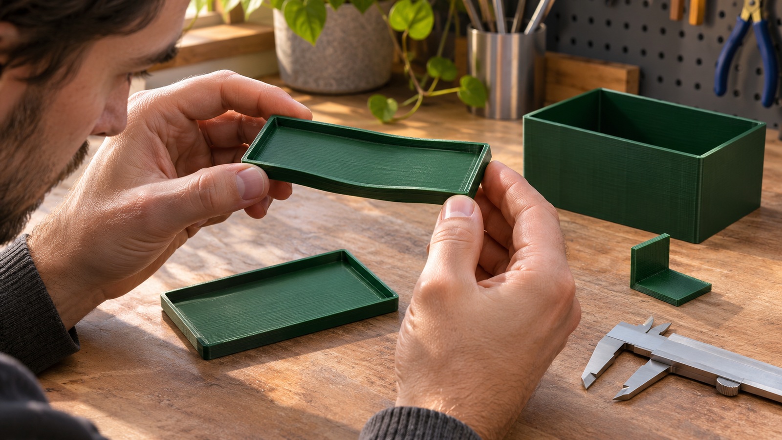
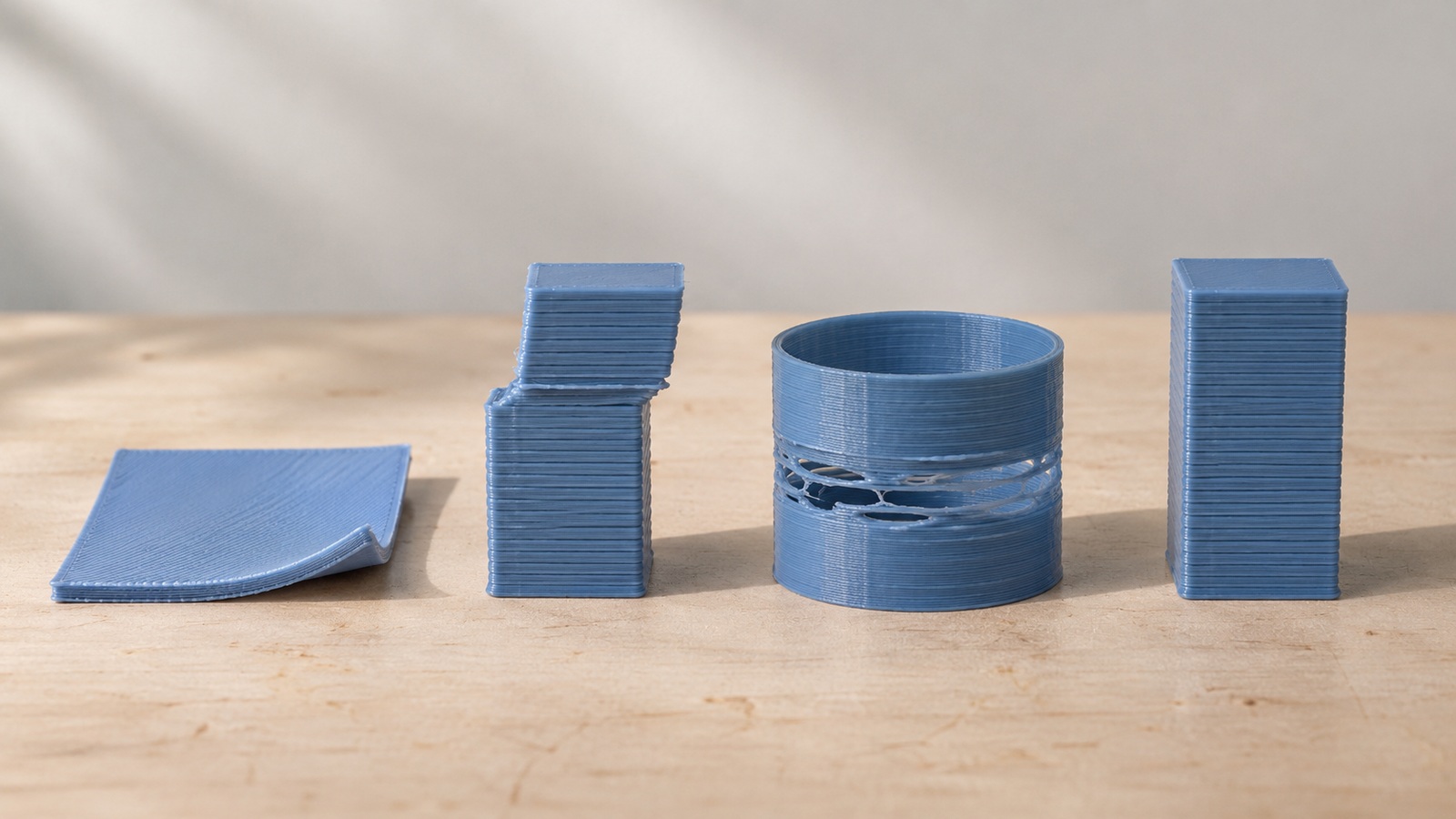
A base that begins flat and later curls is a different symptom from a first layer that never attached. Cooling contraction, temperature differences, geometry, and adhesion can combine to lift corners or distort a broad surface. Start by checking whether the corner was attached initially or never settled at all. Next compare the material’s supported printing environment with drafts or an inappropriate enclosure condition. A large rectangular panel may expose the problem far more strongly than a small rounded test piece.
Do not assume that additional adhesive is the complete answer. The design may concentrate contraction around sharp corners, the bed or chamber conditions may be unsuitable, or the chosen material may need a different production route. A brim or orientation change can help a particular geometry, but the finished part still needs inspection for distortion after removal. A base held down during printing can retain internal stress or reveal curvature later.
When Walls Look Sparse or Extrusion Stops
First check the supply path from the spool to the feed mechanism using the printer’s supported inspection method. Look for a filament strand caught beneath another winding, a reel rubbing against its holder, or a guide path that has become obstructed. An upstream restriction can starve a clear nozzle. If the reel or guide is binding, address that restriction before dismantling the hot end.
Next compare the selected filament and nozzle profile with what is actually installed. A mismatched setup can request material delivery that the arrangement cannot sustain. Look in preview for the intended roads, then compare them with the gaps on the object: missing toolpaths and missing deposited material belong to different branches. Avoid a large flow increase while an unexplained loss of delivery remains.
If the supply path and profile are appropriate but deposition remains weak, move to the documented drive and hot-end inspection. Ground filament at the drive shows that feeding has become unsuccessful, but it does not by itself identify what created the resistance. Prusa’s under-extrusion guidance separates drive, feedstock, cooling, temperature and nozzle causes. Use the relevant procedure to distinguish those possibilities instead of replacing several parts together.
When Failure Appears Only on Longer Jobs
A machine that handles a brief sample but fails during a long build needs an investigation that includes time. The spool may reach a difficult winding region, a cable may move repeatedly through an unfavorable path, or a thermal condition may develop after sustained operation. Record whether the failure follows elapsed time, a particular height, or a location on the build surface. Those patterns are not interchangeable: the same height can correspond to the same geometry, while the same elapsed interval across different jobs may suggest another mechanism. Inspect cooling paths and material delivery through the supported procedures, and preserve machine event information. Do not assume that a successful small cube has ruled out every equipment issue simply because it finished before the original fault usually appeared.
When Fine Strands Join Separate Features
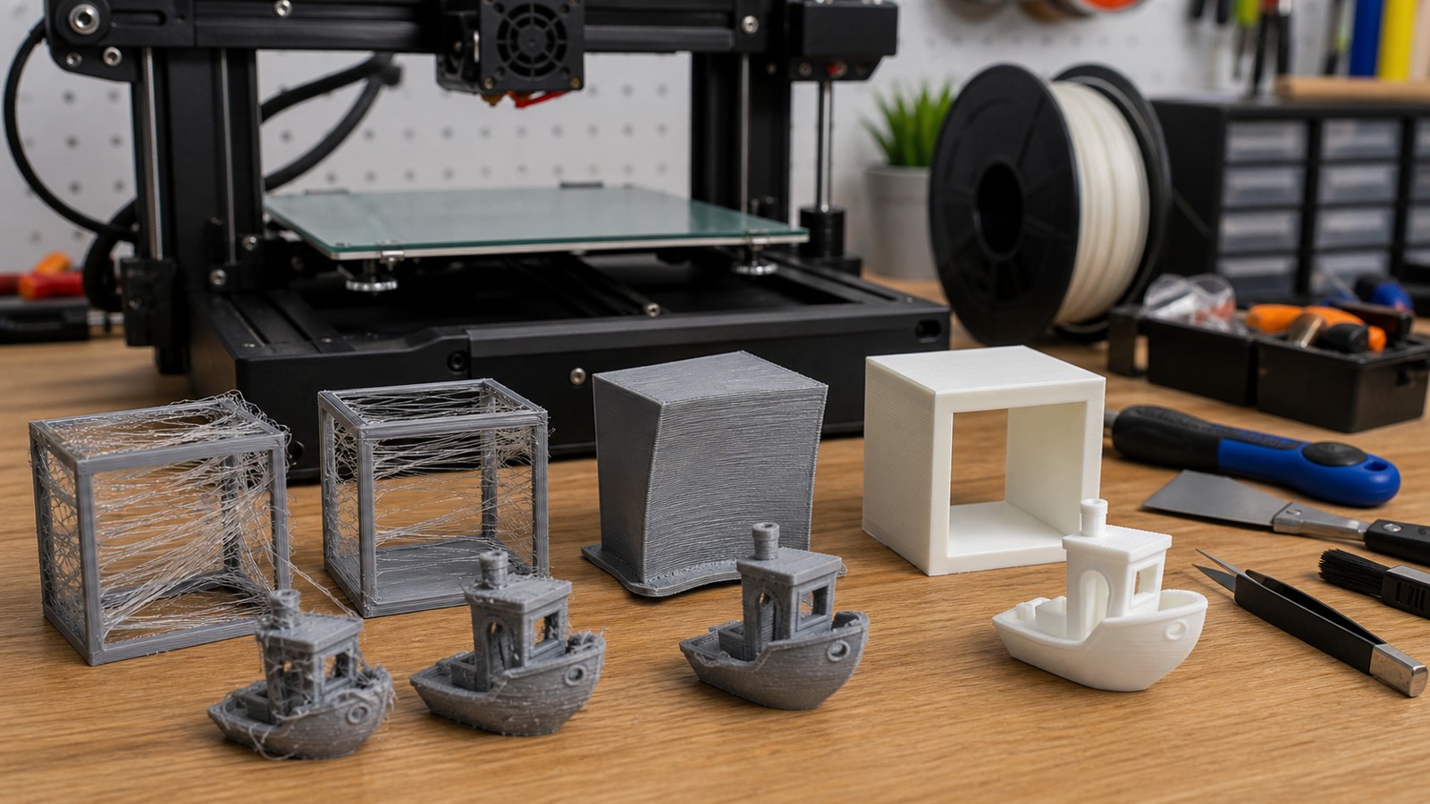
Stringing is material left between regions where the slicer intended a nonprinting movement. Temperature, moisture condition, retraction, travel planning, and the material’s own behavior can contribute. Start by confirming the correct material profile and suitable feedstock preparation. A damp or poorly matched spool can produce confusing symptoms that do not disappear through retraction changes alone.
Look for the difference between fine strands and substantial blobs or dragged deposits. A deposit on a small feature may originate from material collecting on the nozzle, excess delivery, or a region remaining too hot. Those problems need a broader inspection than the label stringing suggests. Also check whether the apparent strand is actually a planned support or feature in the preview before changing settings to remove it.
When Layers Shift Sideways
A layer shift leaves later portions of the model displaced from the earlier geometry. Determine the direction of displacement and the height where it begins. Motion restrictions, slipping attachments, collisions, or a machine being asked to move beyond a reliable operating condition can all be relevant. The direction and timing help narrow which mechanism or event deserves inspection.
Check for evidence of a collision before treating belt tension as the only suspect. A warped edge, curled overhang, loose printed object, or excess deposit can intrude into the nozzle’s path. Increasing tension will not remove that obstruction. Prusa’s layer-shift troubleshooting article emphasizes identifying the affected axis and examining the relevant mechanical conditions.
If the machine reports a motion or collision event, keep that information with the failed sample. A shift that repeatedly appears near the same geometry may have a different explanation from one that occurs at unrelated positions. Do not repeatedly increase motor settings or disable protective behavior to force the job through. Follow the model-specific inspection route and establish that the motion system is usable before another long build.
When Overhangs Sag and Small Peaks Soften
Downward-facing surfaces and tiny upper features can fail even while the broad walls look satisfactory. Overhang angle, support access, bridging distance, cooling, layer timing, and local heat accumulation all influence these regions. Inspect the preview to establish what material is supposed to hold the next path, then evaluate the actual feature at its intended scale. A slower overall print is not always an effective remedy because additional heat exposure or insufficient local cooling can remain part of the problem. Sometimes a new orientation or a modest geometry change removes the difficult condition more reliably than aggressive tuning.
When a Finished Part Breaks or Does Not Fit
A completed build can still be a failed part. Separation along layers, a snapped boss, a binding lid, or a distorted mounting face should be compared with the load path and assembly geometry. Orientation, wall arrangement, material choice, clearance, and processing can all contribute. Examine where the failure began instead of judging the polymer by the fact that the object broke somewhere.
Fit errors also need a distinction between design and manufacturing. An intended gap that is too small may bind even on a reasonably consistent printer, while a localized bulge may point toward an extrusion or surface issue. Measure the feature that controls assembly and compare it with the actual mating part. A single outside dimension from a calibration cube cannot settle every hole, slot, and snap-fit requirement in a new model.
When Resin Prints Stay on the Film or Lose Features
Resin printing introduces different mechanisms, so filament advice should not be transferred directly. A partly formed object remaining on a release surface can involve exposure, support, platform preparation, separation forces, or other machine-specific conditions. Stop and inspect using the manufacturer’s procedure before another attempt. Debris left in the vat can damage equipment or interfere with the next build.
Unsupported islands, unsuitable support connections, and poorly planned hollow regions can also create failures that resemble an exposure problem. Review the prepared layers and the geometry around the first missing region. Check resin compatibility, mixing and conditioning requirements, and the prescribed handling route. A thicker support is not a universal solution if the orientation creates excessive forces or a cavity cannot drain and clean properly.
Judge the object at the correct processing stage. A washed but insufficiently cured sample may not represent the intended final properties, and aggressive support removal can damage an otherwise successful build. Separate printing, washing, curing, and cleanup observations so the actual failed operation remains clear. Use the resin’s product documentation and safety instructions throughout the investigation.
Keep the Explanation Proportional to the Evidence
Several symptoms can occur together without sharing one cause. A warped corner may lead to a collision and then a layer shift, while a separate material condition adds fine strands elsewhere. Address the earliest relevant failure first, then reevaluate the remaining defects on a stable build. Otherwise a small improvement in stringing can distract from the base that still detaches, or a motion adjustment can conceal the collision that continues to develop.
Some printed surfaces also reflect a process limitation rather than a new malfunction. Stair-stepping on a shallow slope, support-contact texture, and directional layer appearance should be compared with a representative sample from the same route. If the requirement exceeds what that route can deliver, consider orientation, geometry, finishing, or another process instead of repeatedly changing settings. An honest boundary is useful troubleshooting information because it prevents a reliable machine from being dismantled in pursuit of an unsuitable target.
Finish With One Clear Next Action
Start with preview, locate the first visible defect, and choose the matching symptom branch. Then perform its first supported check: inspect the supply path for missing material, compare the footprint for attachment problems, or examine the obstruction preceding a shift. Continue to the next check only when the observation gives you a reason to do so. Stop normal operation for damaged wiring, uncontrolled heating or severe mechanical interference and follow the service route. For an ordinary quality fault, the immediate goal is a specific action with an observable result, rather than a collection of upgrades or unrelated settings changes.