Follow the Failure to a Specific Correction
A rectangular box begins printing, but one corner of its base peels away and catches the nozzle. Restarting the job with more glue, more heat, and a different extrusion setting might produce another result without explaining the first one. A useful repair takes a shorter route: identify where the failure began, inspect the conditions responsible for that region, and apply a correction that actually addresses them. This guide follows two clearly illustrative cases rather than claiming hands-on test results. The main example is PLA on an Original Prusa MK4/S with a Smooth PEI sheet; the second concerns a spool obstruction that interrupts feeding. The named procedures come from manufacturer guidance, while the example observations show how to choose between them. Other printers and surfaces require their own supported procedures, especially for calibration, hot-end work, and electrical faults.
A: Yes. Interpret the extrusion component as well as the movement command; a positioning move without requested material delivery is not by itself proof of a blockage.
A: In absolute mode it refers to an extrusion coordinate; in relative mode it describes a change. The same isolated number can therefore mean different requested delivery.
A: No. It resets the logical extrusion reference; it is not itself a retracting movement.
A: In Marlin’s documented command set, M104 sets a hot-end target, while M109 also waits according to its parameters. Temperature-control intent includes that sequencing behavior.
A: It specifies the movement feedrate rather than fan power. Its interpretation belongs to the command and the active unit conventions.
A: No. Marlin documents M220 as a feedrate override and M221 as a flow override. They affect different parts of the requested motion and material relationship.
A: In common G-code syntax it is a comment. Reading a label or explanation in the file is different from identifying a command the firmware executes.
A: The printer needs firmware support for that binary job format. Prusa documents the relevant compatibility requirements; successful preview does not add a missing firmware capability.
A: No. A saved machine state does not reattach or reposition the physical object. Follow the printer’s recovery instructions and assess whether the original build arrangement remains intact.
A: It concerns integrity or sequencing of transmitted commands, rather than whether the original mesh has a hole. The communication problem and the model’s surface topology belong to different stages.
Case One: Find Where the Box Lost Its Attachment
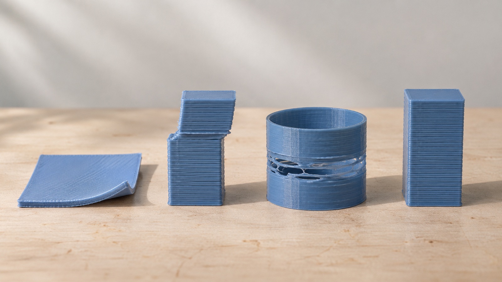
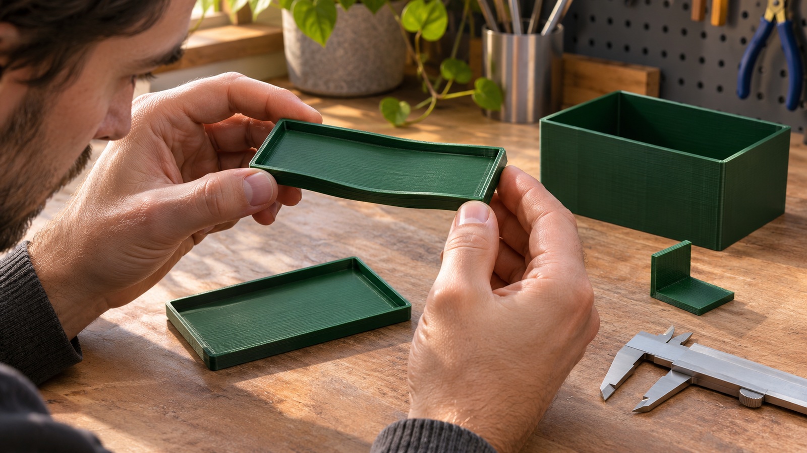
Imagine an open-topped PLA desk box whose base should lie flat. In this example, three corners remain attached while one corner lifts during the early layers. The loose corner then moves when the nozzle passes nearby. Stop the unsuccessful job through the printer’s normal control rather than continuing to deposit material onto a moving base. Let the printer reach its supported handling condition before removing the failed piece. The immediate problem is lost attachment, while the later damaged walls are consequences of continuing above that unstable corner.
Now separate two possible histories. Did the first paths already fail to attach at that location, or did a previously attached base curl upward later? Early paths sliding over the sheet make its contact condition a sensible starting point. A base that stays attached initially and lifts only after substantial walls grow introduces a stronger thermal and geometric question. For this worked route, assume the early paths release where the sheet was handled with bare fingers. That is a plausible contamination clue, not proof from a fingerprint photograph. The next checks determine whether cleaning is an appropriate first correction.
Check the Prepared Footprint Before Touching the Machine
Open the prepared job and inspect the first-layer preview. The planned base should contain the paths needed beneath the box. If the supposed corner is absent there, cleaning cannot make the printer deposit it. Return to the model and preparation instead: check whether the intended base sits on the build surface and whether a thin or damaged feature was omitted. Correct that specific geometry or placement, slice again, and confirm that the corner now has a viable path. This is a different repair branch from material failing to stick where a path already exists.
For the main example, the preview contains a continuous base and the machine attempted those paths, so continue with the contact problem. Confirm that the selected printer, nozzle configuration, and PLA profile describe the installed setup. A file prepared for another machine can introduce unrelated movements or conditions. This check is not a reason to tune every profile field. It prevents the investigation from attributing a preparation mismatch to the sheet while preserving the supported material setup for the cleaning trial.
Keep the rectangular footprint for the repeat. Replacing the box with a tiny central cube would remove the troublesome corner and change the area being investigated. The repeat can be stopped after enough early layers have formed to inspect attachment, using the printer’s ordinary stopping procedure. It should still visit the relevant region and form the same base. That gives cleaning a meaningful test without requiring another complete failed box merely to discover that the first layer remains unsuitable.
Prepare the Actual Sheet for Its Cleaning Method
Identify the surface before choosing the cleaner. This example uses Prusa’s Smooth PEI spring-steel sheet, which differs from its textured, satin, and specialty sheets. The Smooth Steel Sheet guidance specifies cleaning with approximately 90 percent isopropyl alcohol on an unscented paper towel while the sheet is cold. Skin-cleaning products can contain oils and are not interchangeable with that instruction. Prepare the printer and sheet according to their handling guidance, remove the failed material through the supported removal method, and handle the sheet by its edges where practical. Cleaning around a still-attached failed base would leave its contact region untreated.
Apply the Surface Correction and Restore Its Seating
Use the specified IPA on a fresh unscented paper towel and wipe the print-facing surface, including the area beneath the failed corner. Avoid immediately placing fingers back on that cleaned area. Inspect the underside and the receiving bed for loose filament scraps before reseating the sheet. A particle trapped below it creates a different physical problem from grease above it. Restore the sheet in its intended position so the repeat uses a properly seated surface, rather than a clean sheet resting over debris.
If ordinary IPA care has stopped restoring adhesion, Prusa’s first-layer guidance also describes occasional cleaning with a few drops of dish soap and warm water, followed by thorough drying. Follow that route’s limits rather than soaking the sheet in hot water or substituting another household chemical. This is a documented alternative for the relevant sheet condition, not a required second treatment after every wipe. For the illustrative fresh-handling contamination, begin with the routine IPA correction and assess it before escalating the surface treatment.
Do not add glue automatically to this PLA trial. A release layer can be important for other material-and-surface combinations, including some that otherwise bond too strongly, but it is a different purpose from cleaning this sheet for PLA. Nor should acetone advice be transferred to every coating: Prusa excludes it from textured and satin sheets. The selected action here is specific and complete: remove the failed material, clean the appropriate cold surface, clear its seating area, and reinstall it correctly. The repeat can now investigate the contact condition without several unrelated changes competing to explain its outcome.
Read the Repeat While the Relevant Region Is Visible
Start the same prepared footprint with the supported setup and watch the failed corner as its paths form. The useful observation is whether those paths remain located on the sheet and join the surrounding base. A line dragged along by the nozzle has not established a sound beginning, even if another corner looks excellent. Stop again if material is accumulating on the nozzle or the base is moving. Repeatedly laying more plastic over a detached patch makes the evidence harder to read and can create additional cleanup.
If the cleaned surface now holds the early base, the trial supports contamination as a contributor to the original loss of attachment. It does not report a result we obtained, nor guarantee that the rest of the box will remain flat. Continue to the full-height evaluation only when the early layer is suitable. If the same area still releases immediately, the cleaning branch has not resolved the failure. Move to the checks below instead of making the IPA treatment progressively more aggressive or disguising the result with several new slicer settings.
Choose the Next Branch When Cleaning Is Not Enough
First inspect the sheet itself. A damaged film or a local seating problem can remain after grease is removed. Compare the affected area with the condition described in the sheet documentation and use the manufacturer’s replacement or repair route when the surface is unsuitable. Do not assume that every cosmetic mark requires replacement, or that a visibly damaged contact must be rescued by stronger adhesive. The target is an intact, correctly seated surface appropriate for the selected material.
Next consider the printer’s first-layer system. The MK4/S loadcell documentation explains that it checks the first-layer reference automatically before printing; manual Live Z calibration used on other Prusa models is not the corresponding routine. Follow the model’s nozzle-cleanliness and loadcell checks if the first-layer relationship is suspect. Material on the probing nozzle can interfere with the intended contact, but its cleaning must follow the hot-end procedure for that assembly. This guide does not substitute a guessed negative Z offset or an improvised hot-nozzle operation for that process.
Finally, revisit the timing. If the entire base attaches initially but a corner rises as the walls grow, investigate the product’s thermal setup and geometry through the relevant warping guidance. A large sharp-cornered footprint is not the same thermal task as a small rounded one. A supported brim may help attachment for an appropriate model, while a design change can address a difficult corner; neither should be presented as a cure for every later contraction problem. Select the branch supported by the observed event instead of treating every failure involving the bed as an identical leveling fault.
Case Two: Correct an Obstruction Before Changing Extrusion
For a second illustration, suppose a print begins normally, then deposited lines become sparse while the feeder clicks. Inspection shows that a spool flange is rubbing against an object beside its holder, and the roll cannot unwind freely. Stop the job through the supported controls and restore the holder’s intended clearance. Remove the external obstruction, check that the spool is supported correctly, and inspect its route through normal loading or movement checks. Increasing flow would ask the drive for more material without removing the resistance that prevented supply.
A strand trapped beneath another winding needs a different action from a flange rubbing a nearby object. Prusa’s tangled-filament procedure explains how to address the trapped loops while retaining control of the filament tip. Follow that procedure rather than pulling harder on the strand or releasing the end to unwind freely. Once the actual obstruction is removed, use the printer’s supported loading and extrusion checks to establish normal delivery before another complete job. If the roll now turns correctly but feeding still fails, inspect the remaining drive or hot-end problem through its own service route. The visible spool finding may be a contributor without explaining every symptom.
Complete the Successful Branch on the Original Part
In the successful branch of our illustration, the surface correction removes the contamination affecting the early paths. The repeat base stays attached, so the full box is printed with its original footprint and wall height. After the specified cooling and removal, its base sits flat enough for the intended noncritical desk-organizing use, without the original lifted corner. This is an explicitly hypothetical outcome explaining how the repair closes, not a result from a test we performed. The selected correction was cleaning and reseating the appropriate surface; its completion check was the full box after release, rather than an unrelated cube that happened to stick.
The spool case closes through another physical correction. Removing the object rubbing the flange restores the holder’s intended clearance, after which supported loading checks and the intended printing run can establish whether delivery remains normal. Observe the roll as it moves through ordinary winding positions, because one freely moving moment does not exercise every position encountered later. If feeding is restored over that run, there is no reason to invent a new flow multiplier to compensate for the removed obstruction. If it is not restored, the remaining drive or hot-end issue stays open for its own inspection.
Keep the outcome attached to the branch actually followed. A clean early footprint does not settle later thermal warping, while a corrected spool obstruction does not repair damage already present in a failed wall. Restart a failed object through the appropriate supported route instead of treating new extrusion as a repair to its missing layers. If a thermal, electrical, or severe mechanical warning appears, ordinary quality experiments end and the manufacturer’s service process takes over. The useful endpoint is specific: a corrected physical condition and an original task that now works, or a clearly identified unresolved branch requiring further attention.