Start With Design Intent
A good parametric 3D model begins with design intent. Before opening CAD, decide which dimensions may change, which features must stay centered, which holes must keep spacing, and what the part needs to fit.
A: Match the model, material, settings, and finish plan to the purpose of the print.
A: Bed leveling, surface cleanliness, nozzle height, temperature, and material condition are the usual suspects.
A: No. Slower speeds can improve detail, but heat buildup and profile balance still matter.
A: Use the right material, more walls, smart orientation, enough infill, and realistic load testing.
A: Temperature, retraction, travel moves, moisture, and material type all contribute.
A: Diagnose thin walls, unsupported features, tight fits, bad meshes, and weak load paths before buying parts.
A: Very important; it shows toolpaths, supports, layer changes, and possible weak spots before printing.
A: First layers, simple calibration prints, support cleanup, and basic material profiles.
A: Clean orientation, tuned settings, good material handling, and careful test fits, inserts, sanding, assembly, and revision notes.
A: It is most useful for makers designing parts that need to fit, move, or survive use.
Start With Design Intent
A good parametric 3D model begins with design intent. Before opening CAD, decide which dimensions may change, which features must stay centered, which holes must keep spacing, and what the part needs to fit.
For 3D printing, the adjustable values often include width, height, depth, wall thickness, clearance, screw diameter, magnet diameter, slot length, nozzle-friendly radius, and printer tolerance.
Create Named Variables
Most parametric CAD tools allow named parameters or variables. Instead of typing 3.2 mm repeatedly, create a screw_diameter value. Instead of hard-coding every wall, create wall_thickness. The names make the model readable and easier to update.
Useful variables for printed parts include material clearance, press-fit offset, loose-fit offset, layer height assumptions, and minimum wall. These values turn trial-and-error into controlled iteration.
Build Stable Sketches
Sketches are the foundation. Fully constrain important sketches with dimensions and geometric relationships such as horizontal, vertical, equal, concentric, parallel, tangent, and symmetry. Leave only the movement you intentionally want.
A stable sketch updates predictably when a variable changes. An under-constrained sketch may twist, jump, or rebuild incorrectly when the model is edited.
Use Features in a Logical Order
Build the main shape first, then functional cuts, mounting features, patterns, fillets, and cosmetic details. Keep fragile details late in the feature history so core dimension changes do not break the model.
For printed parts, add fillets where stress and layer transitions matter, but avoid tiny fillets that disappear in the slicer. Features should support the print process as well as the CAD model.
Add Configurations for Variants
Configurations let one model produce multiple sizes or versions. Onshape describes configurations as a way to create variations of parts, assemblies, or variable studios. That is useful for size ranges, left/right versions, hole patterns, and product families.
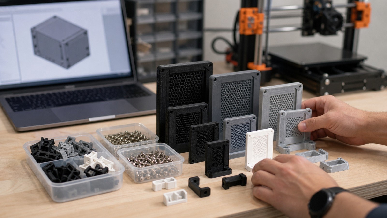
For example, a cable clip could have configurations for 4 mm, 6 mm, and 8 mm cable diameters, all driven from the same core model.
Test With Small Prints
Parametric models still need physical testing. Print a short section, fit gauge, hole strip, or corner sample before printing a full part. Measure the result, adjust the parameter, and re-export.
That feedback loop is where parametric modeling becomes valuable. Each test improves the same model instead of creating a pile of unrelated files.
FAQ
What is the first step in parametric modeling?
Define the design intent and identify which dimensions or relationships need to change later.
Should I use variables in CAD?
Yes for repeated or adjustable values such as wall thickness, clearance, screw size, and part width.
How do I make a model customizable?
Use named parameters, constrained sketches, and configurations so important dimensions can change without rebuilding the part.