Learn the Words Along the Printing Workflow
A beginner can understand a model perfectly well and still feel lost when a tutorial asks for more perimeters, a smaller layer height, a brim, or a different retraction setting. The vocabulary becomes easier when each term is connected to something visible in the printing workflow. A design becomes a file, software turns it into manufacturing instructions, the printer forms layers, and the finished object reveals whether the choices worked. This guide follows that sequence, concentrating on the language commonly used around desktop filament printing while identifying important differences for resin and other processes. You do not need to memorize every abbreviation before making useful objects. Learning what a term describes, where you encounter it, and which problem it helps explain will make tutorials, slicer menus, and troubleshooting discussions much more approachable.
A: It is a linked copy of an object. Changing a shared setting or scale affects the related instances; a separate object can be edited independently.
A: Its usual role is to mark a region receiving different settings, such as denser infill, where it intersects the model. It is not an ordinary additional part.
A: It marks a shape to subtract during slicing, such as a cylinder used to create a hole. That is different from merely changing settings within a modifier region.
A: No. It uses different vertical layer increments over different portions of the build, while the installed nozzle can stay the same.
A: The nozzle makes extra passes across suitable top surfaces with a small material flow to smooth them during printing; it is not an instruction to use a clothes iron afterward.
A: It describes the order in which neighboring lines are laid down, progressing consistently across the area to give a more uniform surface appearance.
A: It completes one object before moving to another, instead of building every object layer by layer together. The printhead must have clearance past completed objects.
A: It receives material during filament or color transitions so the intended object gets a cleaner transition and stable flow. It is auxiliary printed geometry, not part of the model.
A: The base spreads slightly wider than intended, resembling a foot below the walls. Compensation targets that first-layer expansion rather than shrinking the entire model.
A: No. In a slicer that offers the feature, small deliberate perimeter offsets can create a rough texture. An intentionally textured wall should not be diagnosed as a random surface fault.
Find a Term Quickly
The links below are alphabetical, so you can return to an unfamiliar term without rereading the whole guide. Each opens the section that explains the word in context. Related terms share a destination: 3MF · Adhesion · Bed leveling · Bowden · Bridge · Brim · Calibration · Clearance · Exposure · Extruder · Extrusion width · Firmware · Flow · G-code · Hot end · Infill · Layer height · Layer shift · Manifold · Mesh · Nozzle · Orientation · Overhang · Perimeter · Post-processing · Preview · Profile · Raft · Retraction · Seam · Skirt · Slicer · STL · Stringing · Support · Tolerance · Tramming · Under-extrusion · Warping · Watertight · Z offset.
A Model, a Mesh, and a Printable File
A 3D model is the digital description of an object’s shape. It may begin in computer-aided design software, come from a sculpting application, or be reconstructed from a scan. A mesh represents a surface using connected faces, commonly triangles. That surface needs to describe the intended object coherently; gaps, overlapping regions, or ambiguous connections can cause problems when printing software tries to decide what is inside and what is outside.
Watertight and manifold are terms you will encounter during file checks. Watertight generally means that the intended enclosed surface has no open boundary, while manifold describes a locally consistent surface connection. Imagine a supposedly closed box mesh with a triangular face missing: its surface has an open boundary. Now imagine three surface faces meeting along the same edge, rather than the two expected on an ordinary closed shell. That shared edge is a non-manifold connection, making the intended solid difficult to interpret. Repair tools may help, but a successful automatic repair should still be inspected because the software can resolve an ambiguity differently from the designer’s intention.
STL and 3MF are file formats rather than printer types. STL commonly carries a triangulated surface without an explicit unit declaration, so scale must be interpreted correctly by the receiving software. 3MF can carry units and richer manufacturing information. A slicer’s project file may also preserve settings and placement, but the exact content depends on the application. The 3MF Consortium explains the format’s role in carrying information for additive manufacturing.
The Slicer Turns Shape Into a Build Plan
A slicer prepares a model for a selected printing system. For filament printing, it divides the geometry into layers and generates toolpaths describing where the nozzle travels and deposits material. Its profile combines settings for the machine, material, and intended print behavior. The output is often G-code, a command format interpreted by the printer, although not every additive process uses the same instruction format. Software-specific terms in the final FAQ use PrusaSlicer’s documented features as examples, rather than names that every slicer must share.
Preview is the view of the planned layers and paths before manufacturing begins. It can expose missing walls, unexpected supports, gaps, or regions that begin without adequate material underneath. Previewing is different from looking at the original solid model because it shows the slicer’s interpretation. When a feature vanishes in the preview, the printer cannot reproduce it simply because the feature remains visible in the design application.
Layers Describe the Vertical Build Steps
Layer height is the vertical increment used to build successive cross-sections. A smaller value can represent gradual slopes more finely, but it also increases the number of layers and does not automatically solve every detail limitation. Nozzle diameter and extrusion width influence the horizontal roads placed by a filament printer, while resin systems have different optical and material constraints. Resolution is therefore an incomplete term unless the speaker explains which direction or feature is being discussed. A print can have fine vertical steps yet still miss a thin wall, just as a visually smooth surface can contain a dimensional error.
Walls, Perimeters, and Infill Form the Object
Walls or perimeters are the paths that form the outside and inside boundaries of a filament-printed part. Different slicers use slightly different labels, but the concept is the same: these paths define the shell around the object. Top and bottom solid layers close surfaces where the geometry requires a skin. Their arrangement determines whether an otherwise hollow or partially filled structure becomes a usable closed part.
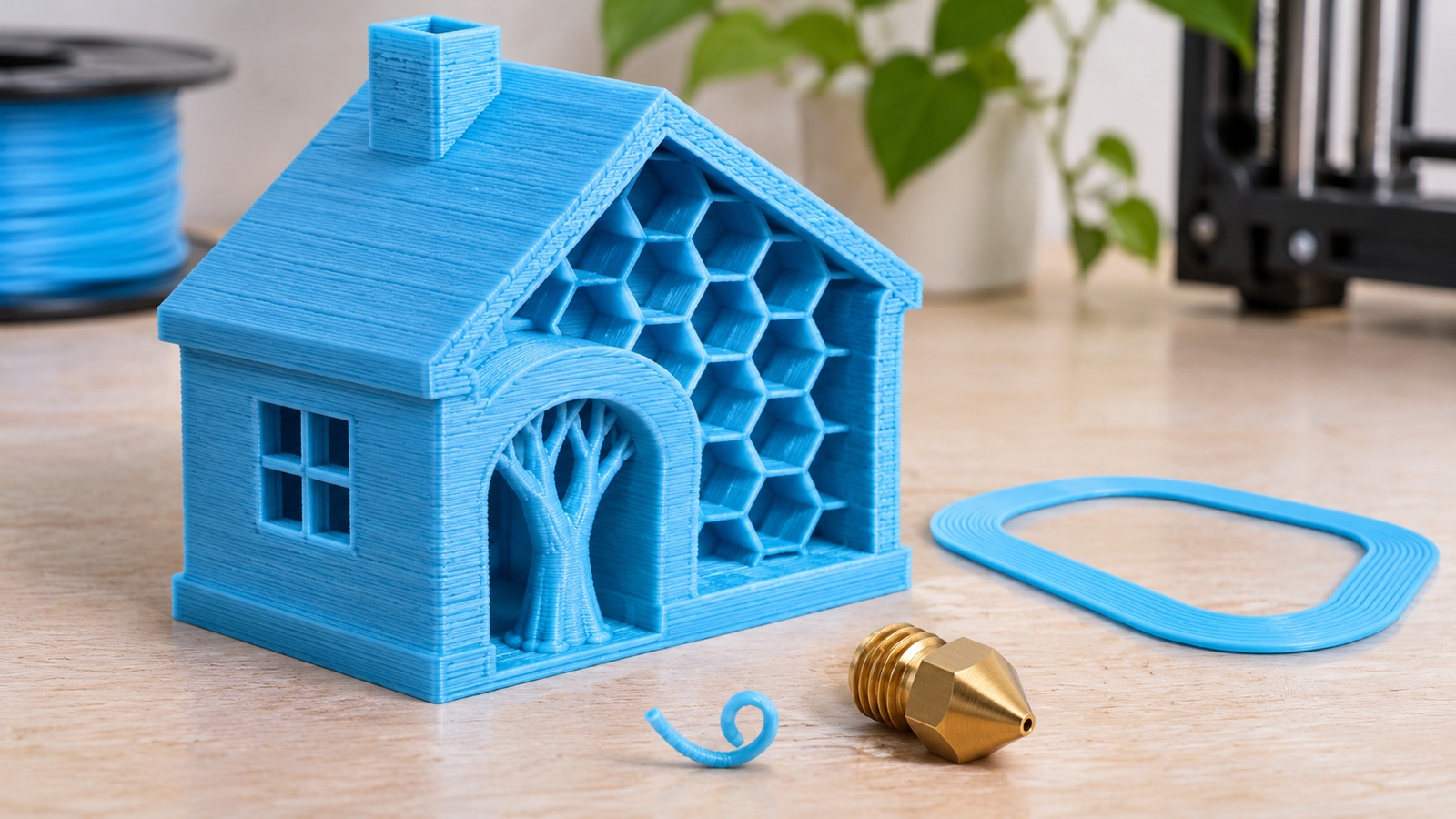
Infill is the internal pattern used inside many filament prints. Its density describes how much of the interior is filled, and its pattern describes the arrangement. More infill does not guarantee the strongest practical part because the walls, orientation, material, and load path also matter. A bracket with inadequate wall structure may benefit more from redesign or additional walls than from filling every internal space.
Extrusion width is the intended width of a deposited road, while flow or extrusion multiplier settings influence how much material is delivered. These terms describe related parts of the process but are not interchangeable. A slicer can intentionally vary path width in suitable situations. Treat a flow adjustment as a controlled calibration change, rather than a general cure for any surface defect that appears on a print.
Overhangs, Bridges, and Supports Solve Different Problems
An overhang is a region extending beyond the material beneath it, so part of a new layer has limited direct support. A bridge spans between supported regions, allowing material to cross a gap under suitable conditions. Support structures are temporary geometry added to hold areas that cannot otherwise print acceptably. Their placement and removal affect surface finish, material use, and the risk of damaging delicate features. Resin supports also deal with the forces of that process, so a support strategy from filament printing should not be transferred blindly to a resin machine.
Skirts, Brims, and Rafts Sit Near the First Layer
A skirt is a detached outline printed around the object, often useful for establishing extrusion and observing early behavior. A brim attaches extra first-layer area around the part’s base, helping hold suitable geometries to the build surface. A raft is a separate foundation printed beneath the object. These features have different purposes and finishing consequences, so selecting one is not simply a matter of choosing the largest outline.
First-layer adhesion describes how well the beginning of the print attaches to the build surface. Build plate, bed, and build surface are related terms, but the removable sheet or coating may have requirements distinct from the underlying heated platform. Cleanliness, temperature, material compatibility, and nozzle-to-surface spacing can all influence the result. Adding a brim may help a particular geometry, but it cannot reliably compensate for every underlying setup problem.
Know the Parts That Move and Melt Material
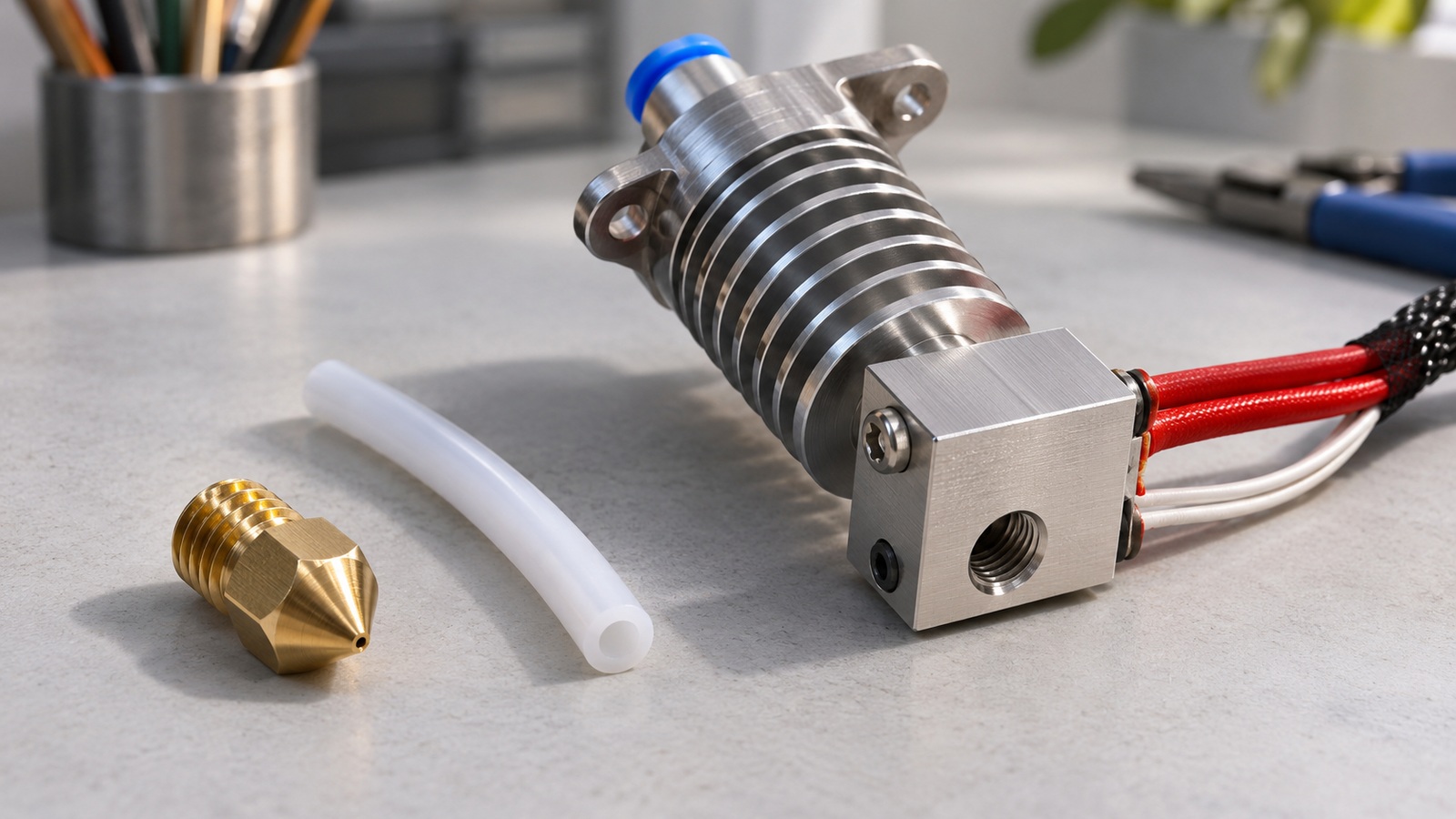
The extruder is the mechanism that grips and advances filament. The hot end is the heated assembly that brings the feedstock to a suitable processing state, and the nozzle is the outlet through which material is deposited. These components work together, but a feed problem at the drive gears is different from a blockage near the nozzle. Knowing the distinction makes maintenance advice much easier to follow.
Direct drive places the filament drive mechanism close to the hot end, while a Bowden arrangement guides filament through a longer tube between a more remote drive and the hot end. Retraction temporarily withdraws or relieves the filament feed during certain movements to help control unwanted material leakage. Suitable retraction behavior depends on the hardware and material. Copying a setting from a different arrangement can create problems rather than solve them.
The motion system positions the tool and build surface according to the machine’s design. Belts, rails, rods, bearings, lead screws, and motors may all appear in maintenance discussions. Firmware is the control software running on the printer, while the slicer prepares the job elsewhere. Keeping those roles separate helps when a tutorial asks you to change a print profile versus update the machine’s control behavior.
Calibration Terms Describe Specific Checks
Bed leveling is often used broadly, but it may refer to mechanically aligning the build surface or measuring its shape for compensation. Tramming describes alignment between the relevant motion plane and the build surface. Z offset adjusts a vertical reference used in positioning, with its exact role depending on the machine and probing system. These terms should be interpreted through the printer’s documentation rather than treated as identical instructions.
Calibration is the process of checking and adjusting a specific behavior against a reference or target. A flow test, dimensional test, or first-layer check examines different things. A calibration cube can reveal some issues, but it does not validate every possible geometry or load condition. Choose the check that corresponds to the problem you are trying to understand, and record the changed setting so the result remains interpretable.
Name Defects by What You Can Observe
Stringing describes unwanted thin strands between regions of a print. Warping describes distortion, often visible when corners lift or a nominally flat feature curves. Under-extrusion refers to insufficient deposited material relative to the intended path, while a layer shift is a displacement that leaves later geometry offset from earlier layers. A seam is the visible region associated with the starts and ends of perimeter loops; aligned starts can leave a vertical line of small marks. These labels describe appearances or outcomes, not a guaranteed single cause. A useful troubleshooting report pairs the term with a photograph, the material, and the stage of the print where the defect first appeared.
Resin Printing Adds Its Own Processing Words
Exposure describes the light applied to cure a region or layer in a resin process. Washing removes uncured liquid from the printed object using the specified procedure, while post-curing applies a further controlled treatment required by many formulations. These operations describe different stages, and neither should be confused with simply waiting for the object to feel dry. Drainage and hollowing refer to design choices that help manage liquid and access inside a model. Their success depends on the actual shape and cleaning route, rather than on adding an arbitrary opening anywhere convenient.
Terms such as build platform, vat, and release film name physical parts of the resin system. The platform supports the growing object, the vat contains resin, and a release interface may separate each newly formed layer from the vat surface in common bottom-up arrangements. Machine designs differ, so component instructions should come from the documentation for the equipment in use. Understanding the vocabulary helps you follow that documentation without importing assumptions from a filament printer. A familiar word such as support can describe a shared purpose while requiring quite different design choices.
Tolerance, Clearance, and Orientation Connect Printing to Use
Tolerance is the permitted variation in a specified dimension or characteristic. Clearance is the intended space between mating features. A hole designed with clearance can still be out of tolerance, and a dimensionally accurate pair can still bind if the design leaves too little space for the surface texture or movement. These distinctions become practical when assembling hinges, lids, sliding parts, and fasteners.
Orientation is the way the model is positioned for printing. It changes support needs, surface quality, and the relationship between layers and service loads. Post-processing describes work performed after the build, including support removal, cleaning, curing, sanding, or machining as appropriate. The printed object and the finished usable part may therefore represent different stages. When discussing a result, state which stage you are evaluating.
Use new vocabulary to make observations clearer rather than to make a problem sound more complicated. Saying that a supported underside is rough gives a more useful starting point than saying that the print has bad quality. Saying that a mating lid binds along one edge narrows the investigation better than asking for perfect accuracy. As the words become familiar, they help you connect the digital model, the machine’s actions, and the finished object’s behavior into one understandable workflow.