Choose a Project for the Lesson It Can Reveal
A shelf full of finished prints does not necessarily show which settings or design choices produced the results. A much smaller collection of deliberate experiments can teach more if each object reveals something you can explain. The most useful learning project has one main aim, a visible outcome, and a manageable next revision. It might show how a first layer joins, how a wall becomes a shell, why a supported underside feels different, or why two parts that look correctly sized still refuse to fit. This guide organizes projects around those skills rather than around novelty or download popularity. The examples focus on desktop filament printing and assume a printer that is already assembled and operating according to its documentation. Three exercises include illustrative dimensions and simple modeling recipes, so you can begin with an actual shape rather than inventing a benchmark. The goal is to finish each exercise knowing what changed and how that knowledge will influence your next useful object.
A: No; a simple shape often makes one important behavior easier to observe.
A: No. The 0.4-millimeter difference is diametral; for perfectly centered ideal circles, the radial space is 0.2 millimeters per side. Printed fit also depends on the manufactured surfaces.
A: With 8-millimeter-wide posts, their centers are 28 millimeters apart. The 20-millimeter dimension measures the empty span between their facing sides, not center-to-center spacing.
A: The cylinder starts on top of the 3-millimeter base. Its 10-millimeter protrusion plus that base gives the 13-millimeter overall height.
A: No; its result is specific to the geometry, material, orientation, and process tested.
A: No. Its ideal corner-to-corner diagonal is about 35.36 millimeters. Check corresponding features when measuring instead of comparing a side length with a diagonal.
A: Subtraction removes only the volume where cutter and block overlap. A cutter that stops inside can leave a blind pocket instead of the intended through-hole.
A: When you want to find out whether the accepted result is consistent.
A: Choose each exercise to resolve an observable uncertainty from the current workflow.
A: You can explain the result and use it to make a reasoned decision on another object.
A First-Layer Tile Makes the Starting Surface Visible
Model a plain square tile 25 millimeters long and 25 millimeters wide using a box primitive in your CAD application. For a profile whose first layer is 0.2 millimeters high, make the tile 0.2 millimeters thick and export it at that size. If your profile uses another first-layer height, match the tile thickness to that value instead. These are illustrative exercise dimensions, not a universal first-layer calibration setting.
Place the broad face on the bed and inspect the sliced preview before starting. The exercise should produce one layer across the intended square, without decoration obscuring the roads. If the file produces several layers or is absent from preview, resolve that preparation issue first. The lesson is observing the printer’s starting surface, not comparing an unknown stack of upper layers.
After normal removal, inspect gaps, raised ridges and differences across the square. Distinguish the top’s deposited-line pattern from the texture transferred by the build surface underneath. Keep the same tile geometry while addressing one observed starting problem through the printer’s supported procedure. That lets the next tile show the effect of the intervention without turning a first-layer exercise into a simultaneous material and geometry experiment.
An Open Box Connects the Preview With the Printed Shell
A small open box makes walls, corners, bottom layers, and internal volume easy to examine. Slice a plain version and follow the paths around its perimeter before printing it. Then compare the physical wall with the preview: identify where the outside boundary, inside boundary, and bottom meet. Change a wall-related setting for a second version only after understanding what the first version contains. The lesson is not that more material is always better. It is that a slicer creates a particular structure, and the structure should be chosen for the object’s purpose. A box that needs to hold light desk items poses different demands from a housing that must keep a fastener aligned under repeated handling.
A Bridge Sample Separates Spanning From Overhanging
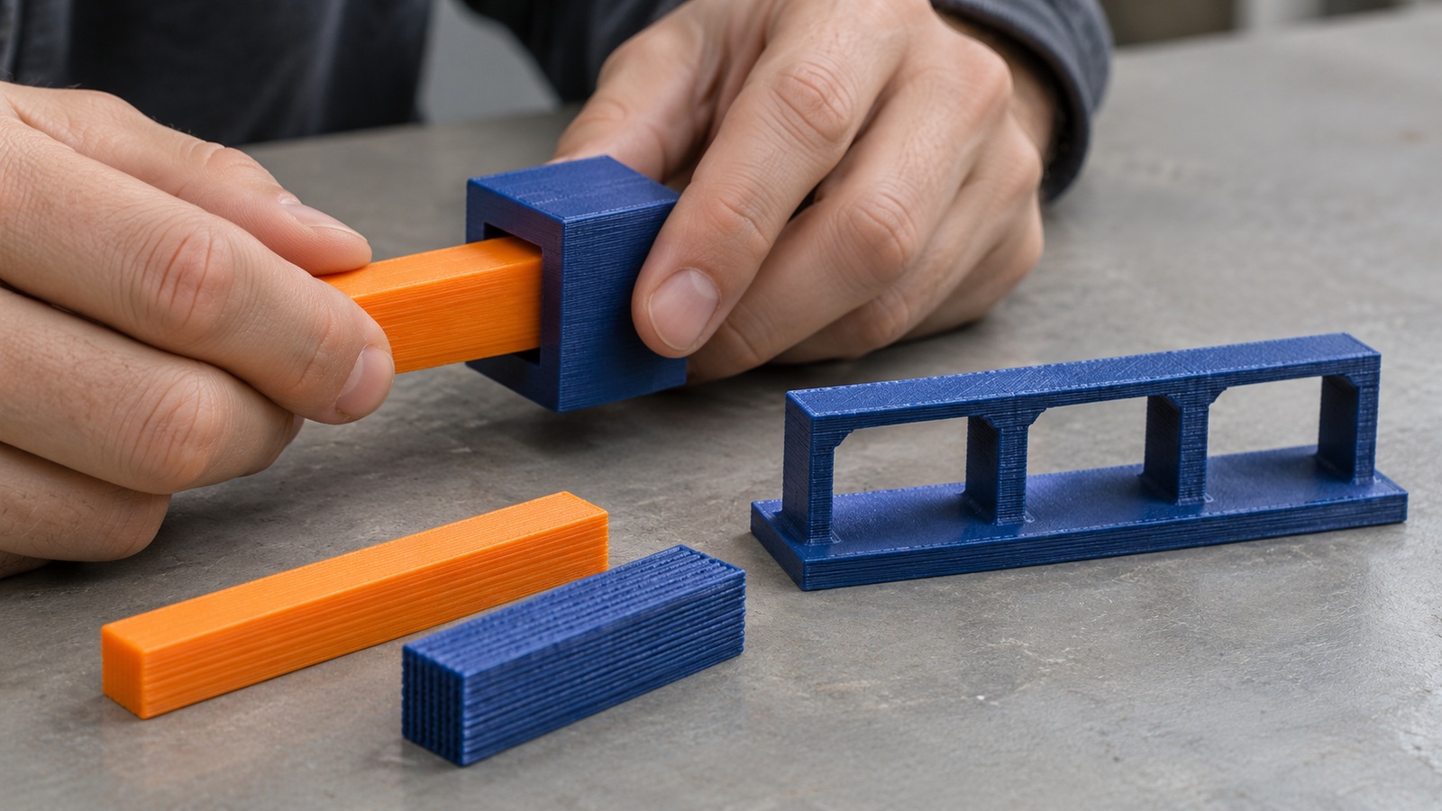
For an original bridge exercise, create two square posts, each 8 by 8 millimeters and 8 millimeters tall. Leave a 20-millimeter clear gap between their facing sides. Join their tops with a rectangular roof 36 millimeters long, 8 millimeters wide and 1 millimeter thick, with its underside at the posts’ 8-millimeter height. The roof overlaps both posts, making one connected sample with an unsupported region between them.
Make optional copies with clear gaps of 10 and 30 millimeters, adjusting each roof length to cover its two posts. Keep post size, roof thickness, material and orientation unchanged. These spans provide a comparison, not a claim that every printer should bridge thirty millimeters. In preview, distinguish the first roof paths crossing the gap from later paths supported by the roof already deposited.
An overhang sample answers a related but different problem. Its successive layers extend beyond the material beneath them, so the shape and angle influence how much support each new path receives. Comparing a simple overhang with a bridge helps prevent the terms from blending into one vague idea of unsupported printing. Material, cooling, path planning and the required underside condition affect which sample you would accept.
Use the result to revise an ordinary design. A small cable-routing opening, for example, might be reshaped to create a more manageable span or remove the need for temporary support. The learning happens when a visible process limit changes the geometry of a useful part. Keep the revised shape beside the sample so you can point to the particular underside or sag that motivated the change.
A Supported Form Teaches Access and Surface Tradeoffs
Select a modest form with one region that genuinely needs support in the proposed orientation. A raised shelf or a short canopy can be easier to understand than an intricate figurine. Inspect the support contact area and the route by which the temporary structure will be removed. After printing, compare the supported face with an upward-facing face of the same object. The difference helps explain why orientation is a finishing decision as well as a way to place a model on the bed.
For a second version, change the orientation or a relevant support-interface choice while leaving the rest of the experiment understandable. Follow the slicer’s documentation for the available support controls. A support that removes easily but leaves an unacceptable surface has not solved the whole problem, and a smooth surface trapped behind inaccessible support is not useful either. Judge the cleaned object, including how long removal takes and whether the feature survives intact. These observations prepare you to discuss support strategy on more complex designs.
A Peg-and-Socket Pair Makes Clearance Concrete
Build a peg by joining a 6-millimeter-diameter cylinder, 10 millimeters tall, to the top of a 12-by-12-by-3-millimeter square base. Center the cylinder on the base and keep it upright for printing. For the sockets, make three separate blocks, each 12 by 12 by 10 millimeters. Cut a vertical through-hole in the center of each, using diameters of 6.2, 6.4 and 6.6 millimeters. A cylindrical cutter extending beyond both faces makes the intended through-hole clear in a simple Boolean-subtraction workflow.
The modeled diametral clearances are therefore 0.2, 0.4 and 0.6 millimeters relative to the same nominal peg. These are illustrative alternatives to investigate, not a recommended fit table for all printers. Print the blocks with the hole axes vertical and compare how the peg enters each one using ordinary hand pressure. Identify the sockets with removable marks outside their bores so the opening is not altered by the label.
Notice where insertion stops: at the entry lip, along the bore, or when the peg’s base reaches the block. Those observations describe different geometry rather than one vague tight fit. A sliding fit, a removable locating fit and a permanent press fit are different goals, so decide which action this exercise should demonstrate. Keep the result tied to the actual geometry, material and orientation before using it to choose a dimension in another design.
Paired Beams Reveal Why Direction Matters
Print two otherwise comparable simple beams with different orientations, choosing a modest geometry that your printer can handle consistently. Inspect the layer direction and identify how the intended bending or pulling action crosses it. A gentle comparison can show that the objects are not mechanically equivalent simply because their outer dimensions match. Avoid treating an informal hand test as a standardized material measurement. Its purpose is to make the relationship between the manufacturing structure and the applied action visible.
Translate that observation into a noncritical functional design, such as a small desk fixture. Ask whether the expected load tends to separate layers, bend a thin arm, or concentrate stress at a sharp corner. Then consider a different orientation, a rib, or a broader transition. The skill is choosing a structure that serves a known force, not searching for a single strongest setting. If a project will carry consequential loads, appropriate engineering validation must replace an informal classroom-style demonstration.
A Measured Remix Connects CAD to the Physical World
Choose a simple object you are permitted to edit, or create a basic model yourself, and change one dimension to match an existing item. A cable guide around a measured lead or a desk holder fitted to a familiar tool can work well. Identify the dimension that controls the fit and distinguish it from the decorative outline. This exercise teaches you to carry an actual measurement into the design, then check how the manufacturing process interprets it.
Keep an editable source file rather than saving only the final mesh. The editable version makes it easier to revise the controlling dimension without repeatedly distorting unrelated features. Check the exported file’s scale when it enters the slicer, especially if software or file formats have changed. The 3MF Consortium’s format overview explains why units and manufacturing information matter when exchanging print data. Regardless of format, the preview should show the object at its intended physical size.
After printing, compare the real mating action with the original design target. If the feature is too tight, identify whether the issue is a design allowance, an unexpected printed shape, or interference elsewhere on the object. Revise the controlling dimension deliberately and retain both versions. You now have a record of how a digital decision affected the physical result. That connection is an essential design skill and often proves more useful than collecting many unrelated ready-made models.
Repeat the Feature and Keep One Useful Observation
Repeat a small accepted exercise without intentionally changing its preparation, then compare the feature that mattered. For a socket, that means the same peg insertion; for the bridge, the underside of the same span. If the repeat differs, investigate the machine and preparation before inventing a new geometric explanation. The comparison asks whether the observed behavior persists, rather than adding another setting experiment.
Keep one compact entry identifying the sample, its setup and the specific observation. A statement such as the peg binds at the first millimeter of the opening tells you more than bad fit. Use that observation to choose the next exercise or dimensional revision, rather than writing a general account of print quality. The record supports the physical lesson; it should not become the main project.
Build Toward a Part With More Than One Requirement
Once the focused exercises are understandable, combine a few skills in a modest useful object. A small storage fixture might need a clean first layer, a deliberate wall structure, a cable opening, and a fit against an existing surface. Identify which earlier sample informs each feature. This keeps the new project connected to evidence while acknowledging that interactions can appear when features share one object. A successful clearance coupon does not eliminate the need to check the complete assembly.
Resist changing every feature after the first combined trial. Decide which requirement failed and identify the smallest meaningful revision. If the object fits but its supported underside is rough, that is a different problem from a latch that cannot move. Preserve what worked while testing the uncertain feature. The result is a practical development cycle that scales beyond beginner projects: define a purpose, prepare a coherent manufacturing plan, inspect the outcome, and revise with a reason.
Essential printing skills therefore grow from attention as much as from machine time. Small projects make their consequences easier to see and cheaper to revisit. A tile, box, span, supported shelf, mating pair, and measured remix can become a personal reference collection whose lessons you actually understand. Choose the next object for the uncertainty it can resolve, then keep its result connected to the way it was made. That approach turns practice into useful judgment rather than a shelf of unexplained successes.