An STL File Describes the Skin of a Shape
A sphere on screen can look perfectly smooth even when its underlying surface is made from many small flat triangles. STL uses that kind of surface description to represent a three-dimensional object. It is a familiar download format for 3D printing because many design tools can export it and many preparation applications can read it. However, an STL is not a complete print recipe, an editable engineering drawing, or a guarantee that a model will manufacture successfully. The distinction explains several beginner surprises: a model opens at the wrong size, a curve looks faceted, a thin feature disappears, or a beautifully rendered download contains geometry the slicer cannot interpret cleanly. This guide explains the format through those practical situations, showing what the triangles describe, which information is missing, and how to check a mesh before turning it into a physical object.
A: They locate one point along the X, Y, and Z coordinate directions. Together, three such points define a triangular facet.
A: Yes. A negative value places a point on the negative side of the chosen origin along an axis; it is not by itself a damaged triangle.
A: No. It is part of the text format’s record structure, not a successful watertightness test.
A: No. Facet records give their own vertex coordinates, so the same corner coordinates can be repeated for neighboring triangles.
A: The normal describes a direction perpendicular to the triangle; a vertex gives the location of one of its corners.
A: It is an 80-byte opening field that can hold identification or other application-written content. It is not the triangle list or a standardized package of printer settings.
A: No. It counts facet records, not separate connected objects or assembly pieces.
A: It describes the byte order used to store multibyte numeric values, rather than the direction in which a printer builds the model.
A: It expresses a number as a power of ten: 2e-3 means 0.002. That notation represents a coordinate value, not a separate triangle or a printing setting.
A: It is an Internet media-type identifier for STL data. It identifies the format being transferred rather than the material or printer profile needed to make the object.
Triangles Approximate the Outside of the Object
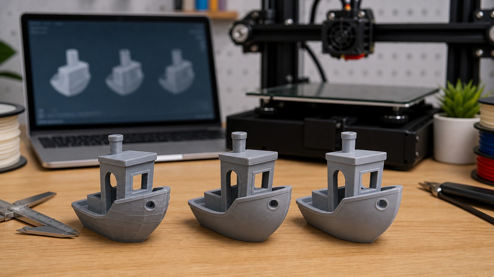
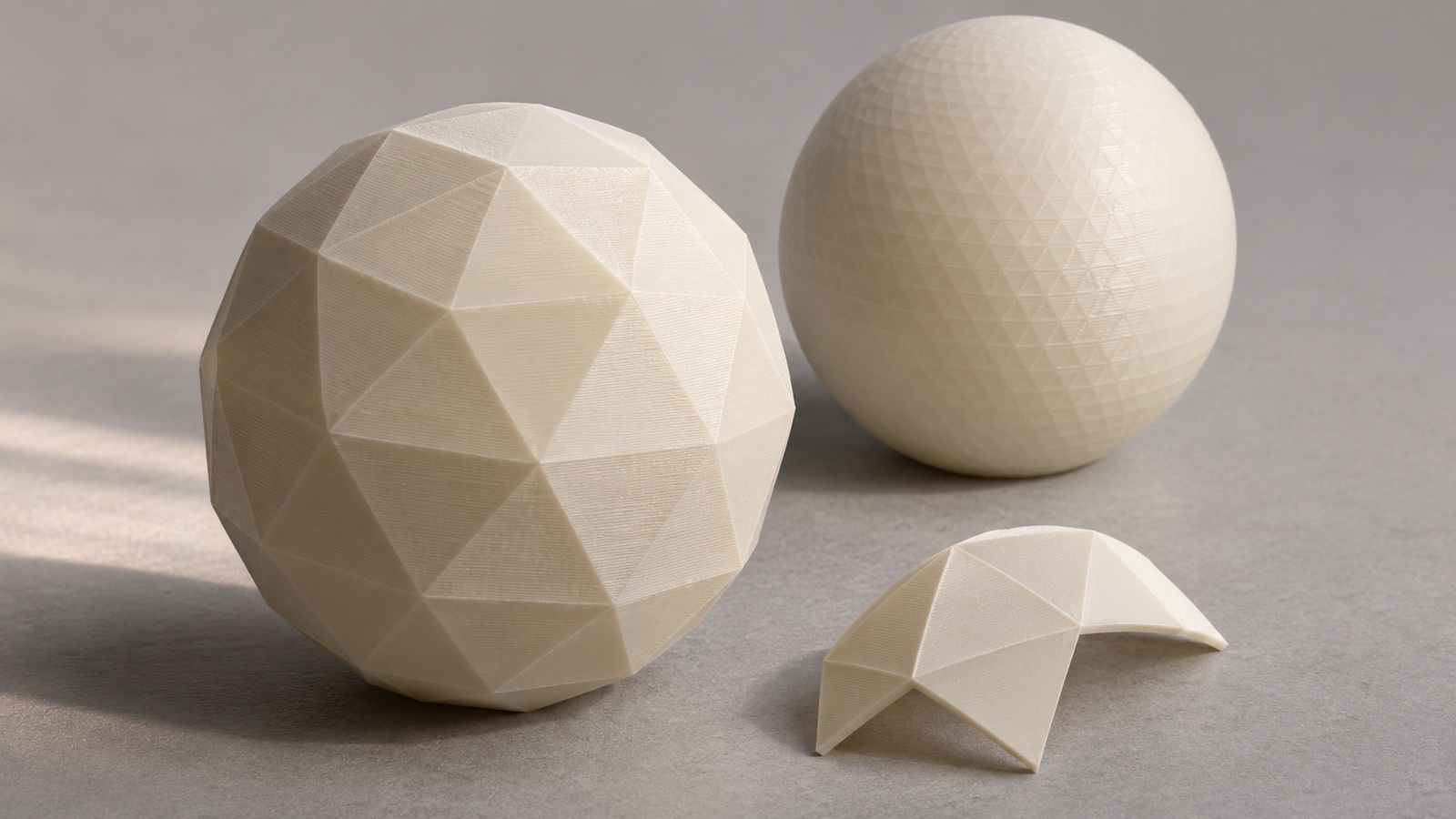
A mesh is a collection of connected faces representing a surface. In STL, those faces are triangles defined by points in three-dimensional space. Large flat regions can be represented with relatively few triangles, while a curved area usually needs more facets to approximate its intended shape closely. The mesh is therefore a geometric description of the boundary, rather than a set of instructions telling a printer how to fill the space inside it.
Imagine wrapping an object in a thin sheet made from flat triangular panels. Smaller panels can follow a curved region more closely, but the panels are still flat. That analogy explains why a low-detail exported sphere can show a polygonal outline even though the original CAD sphere used an exact mathematical surface. The export has replaced that richer representation with a finite approximation.
The file’s triangles also carry an orientation convention used to distinguish the intended sides of the surface. Correctly organized facets help software interpret the boundary consistently. The Library of Congress description of binary STL documents the format’s triangular-facet structure. Beginners do not need to edit those records by hand, but understanding their purpose makes mesh checks much less mysterious.
Closed Surfaces Can Describe Both Solids and Cavities
A slicer needs to determine which regions should become part of the object. A coherent closed boundary gives it a usable description of the intended volume, while holes, overlapping shells, self-intersections, or ambiguous connections can complicate that interpretation. Terms such as watertight and manifold appear in repair tools because they describe aspects of that surface organization. A model can look convincing from the outside and still contain a local defect hidden by shading or by another surface. Inspecting only the attractive rendered view is therefore weaker evidence than examining the mesh and the prepared layers.
Consider a cube whose outside is supposed to enclose material. Removing one triangular face leaves a boundary around the missing patch, so the mesh no longer supplies the same complete enclosure. A different problem appears if three faces share one edge: that branching connection does not continue like an ordinary two-sided surface. These examples explain why an object can look mostly correct yet trigger a mesh warning. An intentionally hollow cup is different again: its inner wall, outer wall, rim, and base can form a closed surface around the material even though the cup has an opening you can pour through.
A model can describe a genuinely hollow region through its boundary surfaces, and that differs from a slicer placing sparse infill inside a nominally solid shape. A designed cavity may need a particular wall, an access opening, or a path for removing process material. Changing an infill percentage does not necessarily create that same geometry or solve its cleanup requirements.
Inspect a cross-section when the distinction matters, especially for a container, housing, or hollow display object. A thin external appearance can conceal an unintended solid interior, while a correctly modeled cavity can remain difficult to manufacture if its openings are unsuitable for the process. Understand which voids belong to the design and which spaces arise from the chosen build strategy. That distinction helps you discuss wall thickness, weight, drainage, and support removal without expecting a general slicer setting to replace a structural design.
STL Does Not Contain the Printer’s Whole Job
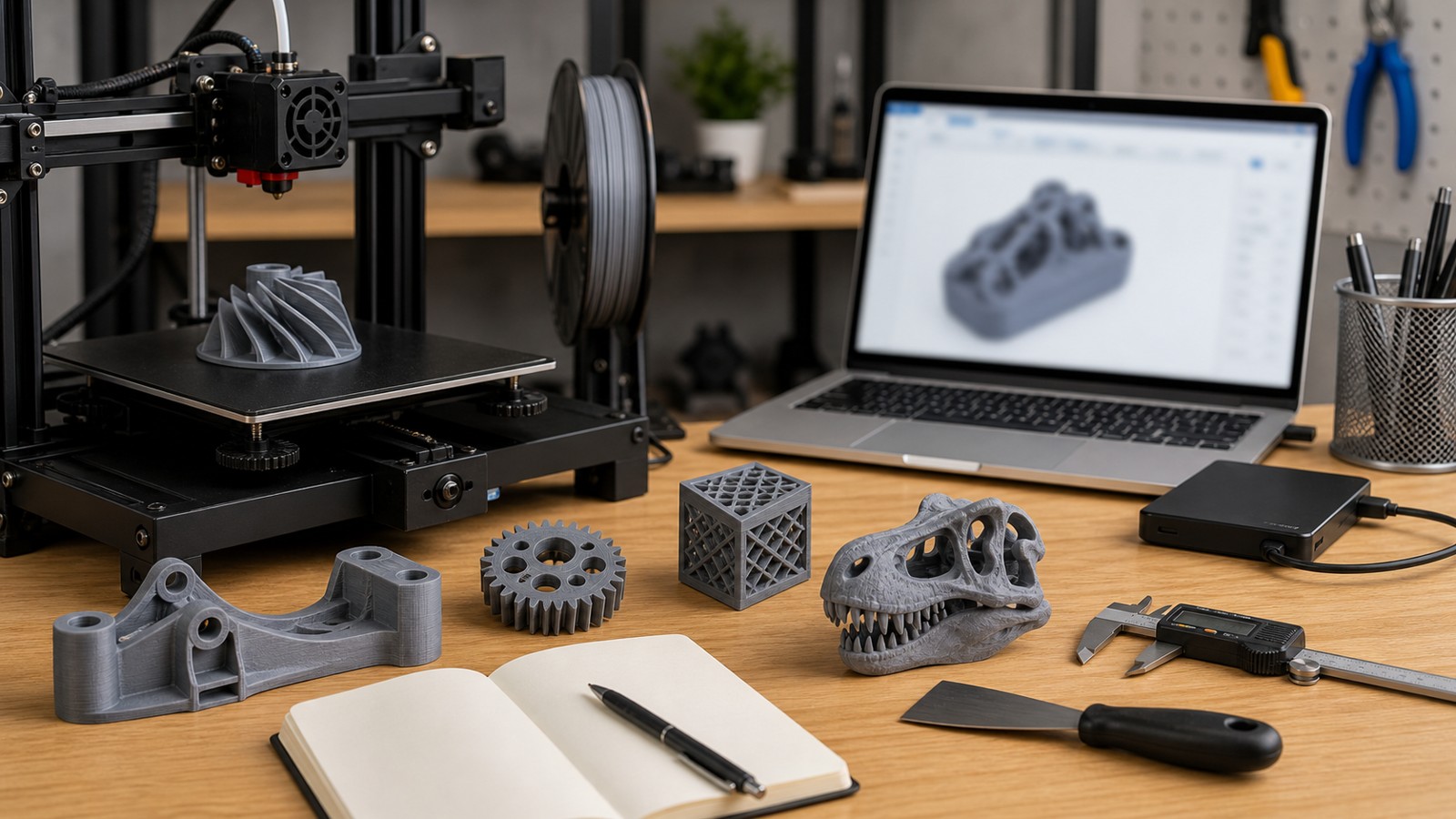
Ordinary STL geometry does not specify a desktop filament printer’s temperature, speed, infill pattern, support strategy, or machine limits. Those decisions belong to preparation in a slicer and to a suitable machine/material profile. Two users can import the same mesh and produce different internal structures or support arrangements. The STL describes the model surface, while the preparation workflow decides how a selected system will build it.
The same distinction explains why an STL is not usually sent unchanged as a finished command stream to a filament printer. The slicer interprets the mesh, creates layers and paths, and writes a suitable output for the selected equipment. Other additive processes have their own preparation routes. A file being widely readable does not mean it bypasses the need to choose and verify those manufacturing decisions.
Scale Needs an Agreed Physical Meaning
STL coordinates provide numerical positions without an explicit standardized unit declaration. Software may interpret those values using a convention or an import option, commonly millimeters in desktop printing workflows. If the sender and receiver assume different units, an otherwise valid model can arrive at an unsuitable physical size. Check the dimensions immediately after import rather than relying on how large the object looks in the viewport.
Use a recognizable feature as a reference, such as an overall length, a hole spacing, or the size of a mating interface. Compare it with information from the designer or a known real object. An extreme mismatch is a reason to establish the original unit convention, not to guess until the model appears plausible. A visual estimate can leave a functional part close enough to look right but too inaccurate to assemble.
Scaling intentionally also changes more than the outside dimensions. Walls, gaps, support-sensitive features, and tiny details change with the object unless a more deliberate design revision is made. A miniature enlarged for display and an enclosure scaled to fit electronics are different decisions. The first may simply need a suitable mesh and print plan; the second can require redesign because its interfaces and wall behavior have functional requirements.
More Triangles Are Not Always More Useful
Mesh detail should suit the intended physical size and manufacturing route. Too few triangles can produce visible flat regions on curves, while an extremely dense mesh can slow editing or slicing without improving a feature the printer cannot reproduce. Increasing density after detail has already been lost does not automatically recover the original shape. When possible, change the export quality from the richer source model. Judge the result at the intended print scale, paying attention to silhouettes, holes, curved mating faces, and other regions where the approximation matters.
Binary and Text STL Describe the Same Kind of Surface
STL is commonly encountered in binary and text-based forms. The binary representation is usually more compact for a comparable set of facets, while a text representation expresses the records in readable characters. Neither choice inherently makes the surface more accurate or the model more printable. The geometric content and its suitability for the job matter more than whether someone can open the file in a text editor.
File size can therefore be a misleading quality indicator. A larger file may contain more triangles, a less compact representation, duplicated geometry, or unnecessary detail. A smaller file may be entirely adequate for a simple shape. Evaluate the surface and the sliced result instead of treating the download size as a rating of the designer’s skill or the final print’s potential quality.
Appearance and Design Intent Usually Live Elsewhere
A conventional STL should be treated as a surface-geometry exchange rather than a dependable carrier for rich color, texture, material, or parametric design information. A preview image on a download page may show paint, lighting, textures, or finishing that are not represented as physical relief in the mesh. Likewise, a CAD feature history containing sketches, constraints, and exact relationships is not recovered merely by opening the STL in a design application. Keep the editable source when available, and consider a supported richer handoff if those properties matter. The 3MF Consortium describes a manufacturing-focused alternative with defined units and broader information capabilities.
Inspect the Download and Its Prepared Layers
Begin with provenance and purpose. Identify the creator, the model version, and any relevant assembly or printing instructions. Check the license before redistributing, modifying for a particular use, or selling objects, rather than assuming that a freely downloadable mesh grants every possible permission. A designer’s photograph can help explain the intended result, but it does not replace information about dimensions, separate pieces, and required hardware.
Open the mesh in appropriate software and inspect it from several directions. Look for disconnected components, unexpectedly thin regions, internal shells, and surfaces that do not form the intended object. A repair warning should prompt review rather than automatic acceptance of whatever the tool chooses to change. If the software closes an opening or merges intersecting regions, confirm that the repaired shape still reflects the intended design.
Then compare the scale and the component count with the instructions. A file containing several pieces may need to be separated or arranged for the chosen process. A model supplied as one visually complete assembly may include contacts that are not intended to become one solid printed object. Establish the intended relationships before making preparation decisions that could fuse, omit, or misplace a component.
Read the Sliced Interpretation
After choosing a suitable machine and material profile, slice the mesh and inspect the planned layers. Pay particular attention to thin walls, small holes, isolated regions, overhangs, and the earliest layers beneath a delicate feature. A surface visible in the original model may disappear if it is too thin or interpreted differently during preparation. The printer cannot form geometry that the actual build plan has omitted.
The preview can also reveal support placement and contact regions that affect cleanup. A support strategy may make the object printable while leaving an inaccessible cavity or a visibly marked surface. These are manufacturing concerns rather than proof that the STL format itself is broken. Use orientation, appropriate preparation, or a deliberate design change to address them, and retain the original mesh so the revision remains traceable.
Editing an STL Is Different From Editing the Original CAD
Mesh tools can move vertices, cut regions, combine surfaces, and perform many useful repairs or modifications. However, a hole represented by facets is not automatically the same as a named diameter feature with an editable constraint. A design application may offer conversion tools, but their result depends on the mesh and the intended operation. If a functional dimension must change repeatedly, obtaining the native design source can be more practical than reconstructing its design intent from a tessellated surface. Treat mesh editing as its own modeling workflow rather than expecting every imported download to behave like a freshly created parametric part.
Keep a Clear Boundary Between Model Quality and Print Quality
A coherent STL can still be unsuitable for a particular printer, material, size, or use. Conversely, a printer can produce a poor result from a reasonable mesh because the preparation or operating conditions are wrong. Distinguish a surface defect in the file from a missing path in the slicer and from a defect that develops only during manufacture. That separation prevents an expensive machine adjustment from being used to solve a geometry problem.
For your first download, choose a modest model with a clear purpose and reliable instructions, check its size, inspect its surface, and review the sliced layers before starting. Save the file together with the preparation project that produced a successful object. As your projects become more demanding, those habits remain useful because they make the handoff from a triangular surface to a usable physical part visible and understandable.