Design for Additive Manufacturing Starts With the Load Path
Design for additive manufacturing, often shortened to DfAM, is the practice of designing a part around the way a 3D printer actually builds it. The strongest printed parts are not simply normal machined parts copied into a slicer. They use geometry, orientation, material behavior, and post-processing as part of the design decision from the beginning.
A: Match the model, material, settings, and finish plan to the purpose of the print.
A: Bed leveling, surface cleanliness, nozzle height, temperature, and material condition are the usual suspects.
A: No. Slower speeds can improve detail, but heat buildup and profile balance still matter.
A: Use the right material, more walls, smart orientation, enough infill, and realistic load testing.
A: Temperature, retraction, travel moves, moisture, and material type all contribute.
A: Diagnose thin walls, unsupported features, tight fits, bad meshes, and weak load paths before buying parts.
A: Very important; it shows toolpaths, supports, layer changes, and possible weak spots before printing.
A: First layers, simple calibration prints, support cleanup, and basic material profiles.
A: Clean orientation, tuned settings, good material handling, and careful test fits, inserts, sanding, assembly, and revision notes.
A: It is most useful for makers designing parts that need to fit, move, or survive use.
Design for Additive Manufacturing Starts With the Load Path
Design for additive manufacturing, often shortened to DfAM, is the practice of designing a part around the way a 3D printer actually builds it. The strongest printed parts are not simply normal machined parts copied into a slicer. They use geometry, orientation, material behavior, and post-processing as part of the design decision from the beginning.
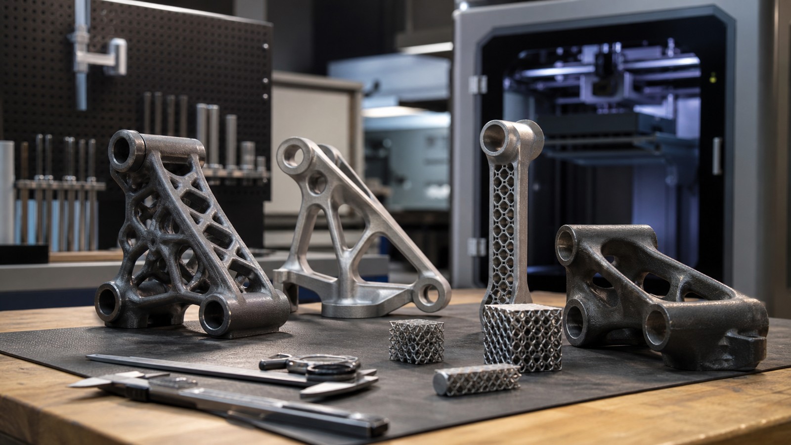
Start by asking where the part carries force. A bracket may fail at a bolt hole, a snap-fit may split along layer lines, and a thin enclosure wall may warp before it ever reaches service. Once the load path is clear, the design can place material where it helps and remove it where it only adds print time, heat buildup, or support scars.
Choose Orientation Before Finalizing Geometry
Print orientation controls surface finish, strength direction, support placement, and dimensional accuracy. In FDM printing, layer adhesion is usually weaker than strength within a layer, so a hook, hinge, or clip should not rely on layers peeling apart under load. In resin printing, orientation affects suction forces, support marks, and how well resin drains from hollow areas.
A practical workflow is to sketch two or three likely orientations before finishing small features. If a tab must resist bending, turn the part so the tab is built with continuous toolpaths rather than stacked layer edges. If a decorative face must stay clean, orient supports toward a hidden surface. A strong part often comes from this tradeoff, not from one magic infill percentage.
Use Walls, Ribs, and Fillets Instead of Excess Infill
For many functional FDM parts, wall count matters more than dense infill. A part with four perimeters and moderate infill can outperform a part with two perimeters and very high infill because the outer shell carries much of the bending load. Ribs, gussets, and boxed sections can add stiffness with less material than simply filling the entire interior.
Sharp internal corners concentrate stress and also create abrupt toolpath changes. Add fillets where loads change direction, especially around screw bosses, hooks, handle transitions, and mounting tabs. Even a 1.5 mm to 3 mm fillet can reduce crack starts in small printed parts while making the printer’s motion smoother.
Respect Process Limits for Holes, Threads, and Clearances
Printed holes often come out slightly undersized, especially on FDM machines, because melted plastic spreads and curved paths are approximated by line segments. A 5 mm peg may need a 5.2 mm to 5.4 mm printed clearance hole depending on the printer, material, and orientation. Test coupons are worth the few grams of plastic when a part has many fitted features.
Threads deserve extra caution. Small printed threads can work for light-duty use, but inserts, captured nuts, or post-tapped holes are usually better for repeated assembly. Heat-set inserts in thermoplastics work best when the boss has enough wall thickness around it and enough depth below the insert to keep the plastic from splitting.
Design Supports Out of the Part When You Can
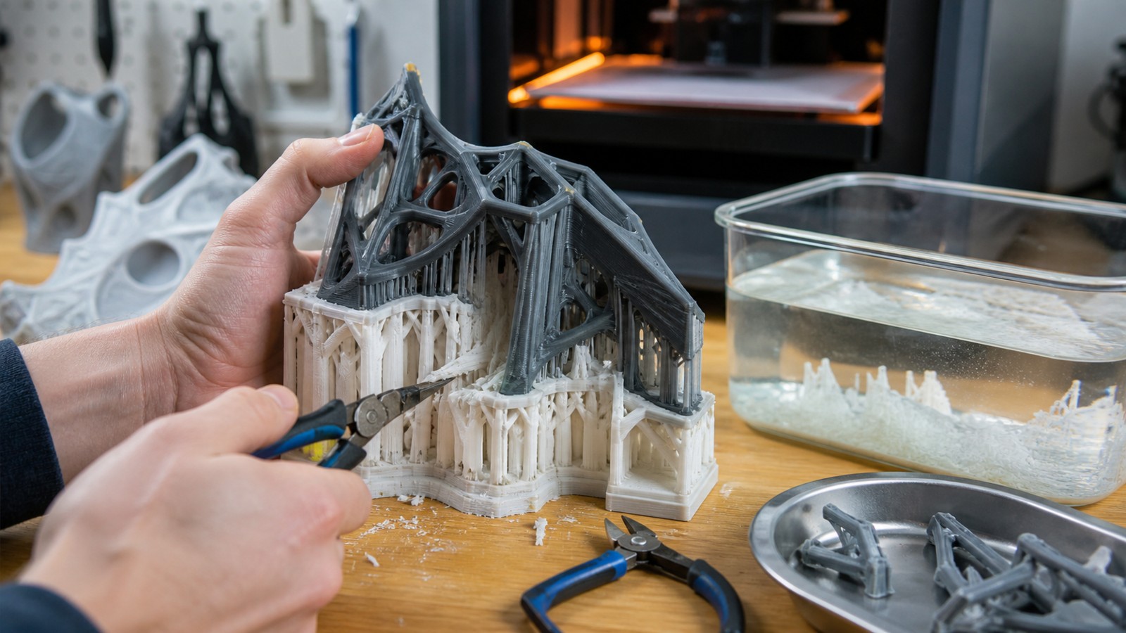
Support material adds time and can damage the very surface that needs to look or function well. DfAM often means changing geometry so the printer can build the part with fewer supports. Chamfers, teardrop holes, self-supporting angles, split assemblies, and flat reference faces can turn a fragile print into a predictable one.
On FDM printers, many materials can handle 45 degree overhangs, but long bridges, thin overhangs, and hot flexible materials need more margin. For resin printing, unsupported islands and heavy cross sections can cause failures even when the final shape looks printable. Good design treats support removal as part of manufacturing, not as cleanup after the fact.
Prototype the Risky Feature, Not the Whole Object
The fastest way to improve a printed part is to isolate the feature most likely to fail. Print a 40 mm section of the hinge, a small strip with the snap-fit, or a corner with the screw boss before committing to a multi-hour job. This confirms tolerances, orientation, and material behavior without wasting a full build plate.
A useful test coupon answers one question at a time. For a lid, test the latch clearance. For a bracket, test the hole spacing and washer contact. For an enclosure, test the corner radius and wall stiffness. A designer who learns from small tests can usually reduce the number of full-size failed prints dramatically.
Match the Material to the Job
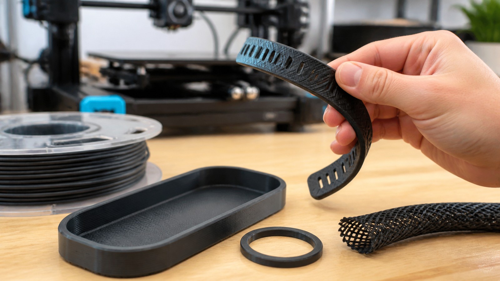
PLA is stiff and easy to print, but it softens in warm environments and can crack under sustained stress. PETG is tougher and more heat tolerant, but it can string and may need more clearance. Nylon, polycarbonate, ASA, and filled composites can be excellent for demanding parts, but they also require better temperature control and more disciplined drying.
Strength is not a single number. A part that needs stiffness, heat resistance, UV resistance, chemical resistance, or impact toughness may point to different materials. DfAM works best when material choice is made alongside geometry, because a flexible clip, a rigid spacer, and a heat-exposed fixture need different shapes even when they look similar.
A Practical DfAM Checklist
Before printing a functional part, confirm five details: the main force direction, the preferred orientation, the minimum wall thickness, the tolerance strategy, and the support-removal plan. For small FDM parts, a common starting point is 1.2 mm to 2.0 mm walls, three to five perimeters, and clearance tests in 0.1 mm or 0.2 mm steps.
For larger parts, think about heat and shrinkage as much as strength. Add relief cuts or divide the design into bolted sections when broad flat surfaces are likely to curl. Use thicker mounting pads where screws clamp the part, and avoid thin isolated towers that cool unevenly. The best design is usually the one that prints reliably, assembles cleanly, and fails predictably if overloaded.
FAQ
What is the most important DfAM rule for stronger 3D printed parts?
Begin with the load path and print orientation. If the layers are aligned poorly for the forces the part will see, high infill alone will not make the part dependable.
Does more infill always make a part stronger?
No. Wall count, shell thickness, ribs, fillets, material choice, and orientation often matter more than raising infill from moderate to very high values.
Should every functional part be printed as one piece?
Not always. Splitting a design into simpler printed sections can reduce supports, improve layer direction, and make assembly stronger with screws, pins, or inserts.